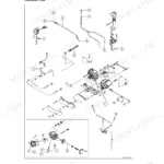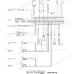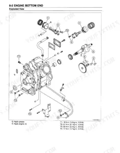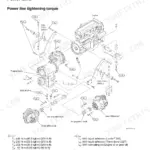


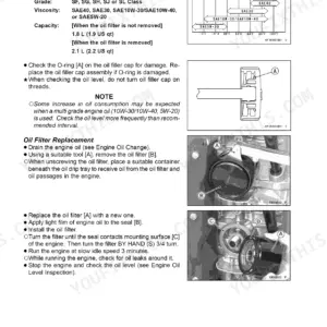
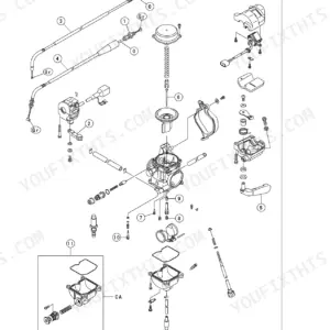
This is the genuine Kawasaki factory service manual for the Prairie 700 4x4, covering the KVF700-A1 and KVF700-B1. It is the same 509 page book dealer technicians work from, delivered as a downloadable PDF, with 18 chapters running from Periodic Maintenance through Fuel System, Converter System, Final Drive, Brakes, Suspension, and a full Electrical System section backed by a troubleshooting appendix.
If you have ever stood over this quad with the covers off and nobody to call, this is the book that answers the question you were about to post on a forum. Torque values, clearances, fluid capacities, and step by step removal and installation procedures are all laid out the way the factory wrote them.
Because it is a PDF, it goes wherever the machine is: a phone in the shed, a tablet in the truck bed, or printed pages spread on the bench.
What's Inside This Kawasaki Prairie 700 4x4 (KVF700) Manual
| System | Pages | Key Topics |
|---|---|---|
| General Information | 6-17 | Before Servicing, Model Identification, General Specifications |
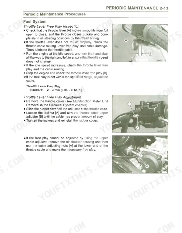
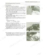
| Periodic Maintenance | 18-56 | Periodic Maintenance Chart, Torque and Locking Agent, Periodic Maintenance Procedures |
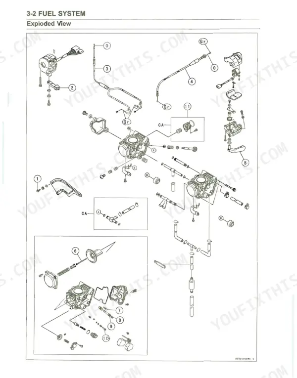
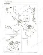
| Fuel System | 57-87 | Carburetor, Air Cleaner, Fuel Tank |
| Cooling System | 88-107 | Water Pump, Radiator, Thermostat |
| Engine Top End | 108-153 | Camshaft, Cylinder Head, Valves |
| Converter System | 154-181 | Drive Pulley, Driven Pulley |
| Recoil Starter | 182-185 | Recoil Starter Removal, Recoil Starter Installation, Recoil Starter Inspection |
| Engine Lubrication System | 186-197 | Oil Pump |
| Engine Removal/Installation | 198-202 | Engine Removal, Engine Installation |
| Crankshaft/Transmission | 203-230 | Crankcase, Transmission |
| Wheels/Tires | 231-244 | Wheel Alignment, Tires |
| Final Drive | 245-311 | Output Bevel Gears, Front Final Gear Case, Rear Final Gear Case |
| Brakes | 312-336 | Master Cylinder, Calipers, Brake Discs |
| Suspension | 337-355 | Shock Absorbers, Suspension Arms, Swingarm |
| Steering | 356-368 | Steering Maintenance |
| Frame | 369-391 | Fenders, Covers, Guards |
| Electrical System | 392-483 | Charging System, Ignition System, Electric Starter System |
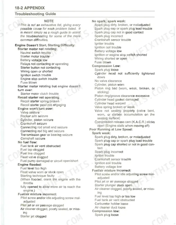
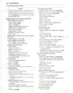
| Appendix | 484-509 | Troubleshooting Guide, Cable, Wire, And Hose Routing |
Quick Reference Specifications
| Specification | Value | Page |
|---|---|---|
| Belt height (parallel portion) standard | 1.16 - 3.48 mm | p. 27 |
| Belt height (parallel portion) service limit | 0.64 mm | p. 27 |
| Service fuel level | 15 ± 1 mm | p. 62 |
| Float height | 4.0 ± 1 mm | p. 62 |
| Rocker Shaft Diameter Standard | 11.973 - 11.984 mm | p. 124 |
| Rocker Shaft Diameter Service Limit | 11.95 mm | p. 124 |
| Actuator lever guide shoe (Service Limit) | 6 mm (0.24 in.) | p. 159 |
| Actuator Lever Assembly Installation Length | 149.33 - 150.47 mm (5.879 - 5.924 in.) | p. 164 |
| Rear shock absorber spring preload setting position standard | Spring free length minus 29.9 mm (1.18 in.) | p. 340 |
| Rear shock absorber spring preload setting position service limit | Spring free length minus 22.9 mm (0.90 in.) to 36.9 mm (1.45 in.) | p. 340 |
| Brake Lever Oil Seal [D] | 14.5 ± 0.1 mm (0.571 ± 0.004 in.) | p. 354 |
| Propeller Shaft Oil Seal [F] | 25 ± 0.1 mm (0.984 ± 0.004 in.) | p. 354 |