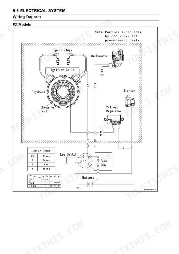
Hunting for a Kawasaki FR651V service manual PDF that actually covers your engine? This 169-page factory service manual (OEM #99924-2093-03) breaks down the FR651V, FR691V, FR730V, FS651V, FS691V, FS730V, FX651V, FX691V, and FX730V 4-stroke air-cooled V-twin gasoline engines in one document. You get factory wiring diagrams for the ignition and charging circuits on pages 149 to 151, a full troubleshooting section covering hard starting, power loss, erratic running, and starter motor faults, plus step-by-step procedures for the carburetor, governor linkage, valve train, and pressurized lubrication system. Set valve clearance at 0.10 to 0.15 mm, then pull the cylinder head bolts down to 46 N-m (34 ft-lb). No more chasing wiring faults with a multimeter and a prayer. Every chapter is bookmarked, so the PDF jumps straight to Fuel System or Electrical System on your phone or tablet in the shop, and the text is searchable when you need a spec by keyword.
What's Inside This Manual
| System | Pages | Key Topics |
|---|
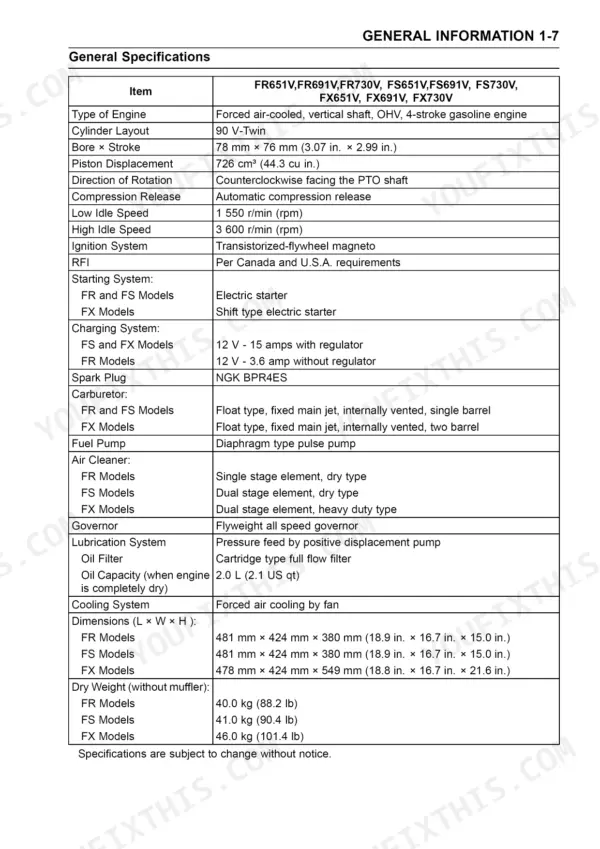
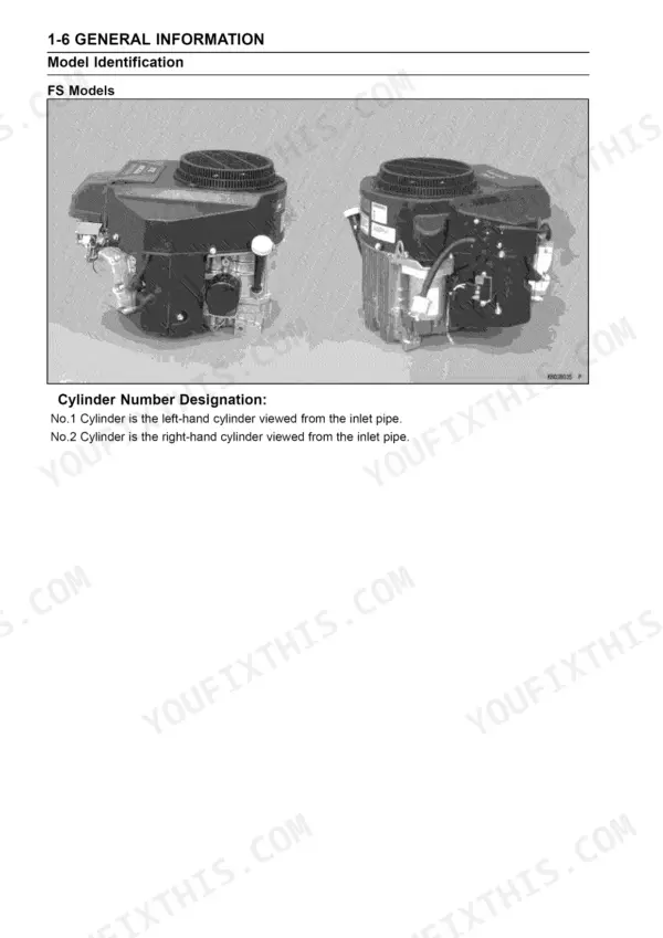
| General Information | 7-13 | Before Servicing, Model Identification (Fr/Fs/Fx), General Specifications |
| Periodic Maintenance | 14-30 | Periodic Maintenance Chart, Torque and Locking Agent, Special Tools, Valve Clearance Inspection and Adjustment, Spark Plug Service, Engine Oil and Oil Filter Change, Air Cleaner Element Cleaning |
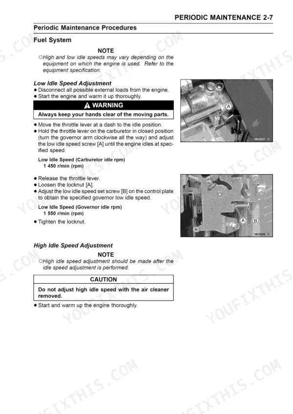
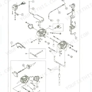
| Fuel System | 31-68 | Exploded Views, Carburetor Removal and Installation, Fuel and Air Flow, Main Jet Replacement, Governor Link Mechanism, Control Panel Assembly, Inlet Manifold, Fuel Pump and Fuel Filter, Fuel Flow Test, Air Cleaner |
| Cooling System | 69-74 | Exploded View, Cooling Fan Removal, Installation and Inspection, Engine Shroud Removal and Installation |
| Engine Top End | 75-97 | Compression Measurement, Cylinder Head Assembly Removal and Installation, Push Rod Installation, Valve Clearance, Valve Guide Inside Diameter, Cylinder and Piston, Piston Ring End Gap, Piston Diameter, Honing |
| Lubrication System | 98-108 | Engine Oil Flow Chart, Pressurized Lubrication System, Engine Oil and Oil Filter, Oil Pressure Measurement, Oil Pump and Relief Valve, Oil Screen |
| Camshaft/Crankshaft | 109-128 | Crankcase Cover Removal and Assembly, Breather Valve Removal and Inspection, Camshaft and Tappet, Camshaft Assembly, Crankshaft and Connecting Rod, Main Journal Wear |
| Starter System | 129-143 | Starter Motor Removal and Installation, Starter Solenoid and Circuit Test, Armature Inspection, Yoke Assembly, Carbon Brush Service Limit, Pinion Clutch |
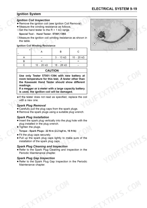
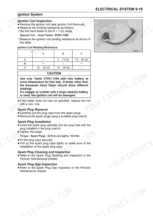
| Electrical System | 144-162 | Wiring Diagrams (Fx, Fr and Fs Models), Precautions, Charging System, Flywheel and Stator Coil, Stator Coil Resistance, Regulator Installation, Ignition System, Ignition Coil Removal and Inspection |
| Troubleshooting | 163-169 | Engine Troubleshooting Guide, Starter Motor Troubleshooting Guide |
Quick Reference Specifications
| Specification | Value | Page |
|---|
| Cylinder Head Bolts (L = 50 mm) torque | 46 N·m (4.7 kgf·m, 34 ft·lb) | p. 16 |
| Cylinder Head Bolts (L = 60 mm) torque | 46 N·m (4.7 kgf·m, 34 ft·lb) | p. 16 |
| Connecting Rod Big End Cap Bolts torque | 9.8 N·m (1.0 kgf·m, 87 in·lb) | p. 16 |
| Valve Clearance (Inlet, Exhaust) | 0.10 ~ 0.15 mm (0.004 ~ 0.006 in.) | p. 18 |
| Spark Plug torque | 22 N·m (2.2 kgf·m, 16 ft·lb) | p. 75 |
| Spark Plug Gap | 0.7 ~ 0.8 mm (0.028 ~ 0.031 in.) | p. 18 |
| Carburetor and Inlet Pipe Mounting Nuts torque | 5.9 N·m (0.60 kgf·m, 52 in·lb) | p. 16 |
| Main Jet torque (FR and FS Models) | 2.3 N·m (0.23 kgf·m, 20 in·lb) | p. 16 |
| Valve Clearance (when cold) Inlet, Exhaust | 0.10 ~ 0.15 mm (0.004 ~ 0.006 in.) | p. 24 |
| FX Models primary element replacement interval | 250 hrs | p. 22 |
| FX Models secondary element replacement interval | 500 hrs | p. 22 |
| Connecting Rod Big End Cap Bolts | 9.8 N·m (1.0 kgf·m, 87 in·lb) | p. 16 |