



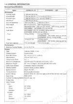
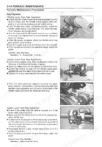
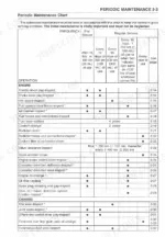
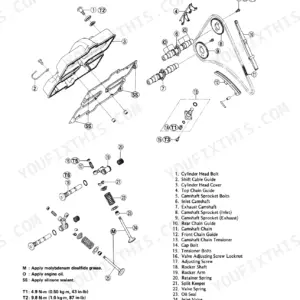
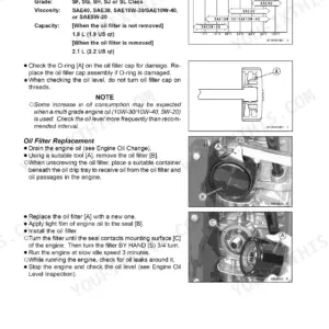
Need factory answers for your 2005-2009 Brute Force? This 528-page Kawasaki Brute Force 650 4x4 service manual PDF (OEM #99924-1348-05) covers the KVF 650 line. Inside: complete electrical wiring diagrams, a factory troubleshooting guide, exploded views of every assembly from the carburetor to the rear final gear case, and torque tables for the whole machine. You also get full cable, wire, and hose routing charts, the stuff that separates a clean rebuild from a rat's nest. Check your CVT drive belt against the 29.7 to 30.3 mm width spec, and torque the 2WD/4WD actuator mounting bolts to 8.8 N-m (78 in-lb). No more chasing electrical gremlins with forum guesses. Bookmarked with a full text layer; search any spec, jump to any chapter, fix your quad.
What's Inside This Kawasaki Brute Force 650 4x4 / KVF650 (2005–2009) Manual
| System | Pages | Key Topics |
|---|---|---|
| Quick Reference Guide | 2-8 | |
| General Information | 9-20 | Model Identification, General Specifications |
| Periodic Maintenance | 21-60 | Maintenance Chart, Torque and Locking Agent, Specifications, Periodic Maintenance Procedures |
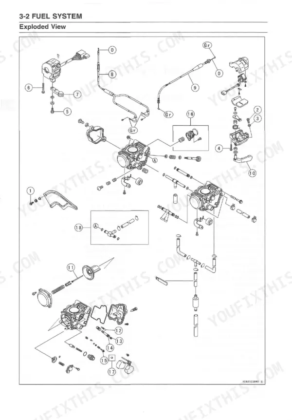
| Fuel System | 61-96 | Exploded View, Specifications, Throttle Lever and Cable, Choke Lever and Cable, Carburetor, Air Cleaner, Fuel Tank, Fuel Pump |
| Cooling System | 97-118 | Exploded View, Coolant Flow Chart, Specifications, Coolant, Water Pump, Radiator, Thermostat, Radiator Fan Switch |
| Engine Top End | 119-162 | Exploded View, Specifications, Special Tools & Sealant, Camshaft Chain Tensioner, Rocker Case, Camshaft, Cylinder Head, Valves |
| Converter System | 163-190 | Exploded View, Specifications, Torque Converter, Drive Belt, High Altitude Setting Information |
| Recoil Starter | 191-206 | Exploded View, Special Tools & Sealant, Engine Oil Flow Chart, Oil Pressure Relief Valve, Oil Pump, Oil Pipe |
| Engine Removal/Installation | 207-212 | Exploded View |
| Crankshaft/Transmission | 213-238 | Exploded View, Specifications, Special Tools & Sealant, Crankcase, Crankshaft/Connection Rod, Transmission, Ball Bearing, Needle Bearing |
| Wheels/Tires | 239-252 | Exploded View, Specifications, Special Tool, Wheel Alignment, Wheels (Rims), Tires, Front Hub, Rear Hub |
| Final Drive | 253-316 | Exploded View, Specifications, Special Tools, Output Bevel Gears, Front Propeller Shaft, Front Axle, Front Final Gear Case, Rear Propeller Shaft |
| Brakes | 317-340 | Exploded View, Specifications, Special Tool, Brake Fluid, Master Cylinder, Calipers, Brake Pads, Brake Discs |
| Suspension | 341-360 | Exploded View, Specifications, Special Tools, Shock Absorbers, Suspension Arms, Swingarm |
| Steering | 361-376 | Specifications, Special Tools, Steering Maintenance, Handlebar |
| Frame | 377-400 | Exploded View, Seat, Carriers, Fenders, Covers, Guards, Flaps and Footboards, Trailer Hitch Bracket |
| Electrical System | 401-498 | Parts Location, Exploded View, Specifications, Precautions, Electrical Wiring, Battery, Charging System, Ignition System |
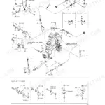
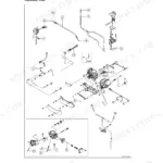
| Appendix | 499-528 | Troubleshooting Guide, Cable, Wire, And Hose Routing |
Quick Reference Specifications
| Specification | Value | Page |
|---|---|---|
| Carburetor | modified | p. 5 |
| Belt Width | 29.7 ~ 30.3 mm (1.169 ~ 1.193 in.) | p. 31 |
| Belt Deflection | 22 ~ 27 mm (0.87 ~ 1.06 in.) | p. 31 |
| 2WD/4WD Actuator Mounting Bolts | 8.8 N-m (0.90 kgf.m, 78 in-lb) | p. 29 |
| Torque - Reservoir Cap Screws | 1.5 N·m (0.15 kgf·m, 13 in-lb) | p. 54 |
| Torque - Bleed Valves | 7.9 N·m (0.80 kgf-m, 69 in-lb) | p. 54 |
| Pilot Jet | #40 | p. 68 |
| Carburetor Pilot Screw Setting Standard | 2 1/4 turns out | p. 74 |
| Float Height Standard | 4.0 ±1 mm (0.16 ±0.04 in.) | p. 76 |
| Belt Height (Parallel Portion) | 1.16 ~ 3.48 mm (0.0457 ~ 0.1370 in.) | p. 168 |
| Ignition Coil: 3 Needle Arcing Distance | 7 mm or more | p. 412 |
| Ignition Coil: Primary Winding Resistance | 0.09 ~ 0.13 Ω | p. 412 |
Kawasaki Brute Force 650 4x4 / KVF650 (2005–2009) Common Problems This Manual Covers
Kawasaki Brute Force 650 4WD won't engage from the handlebar switch, no warning lights on the dash
Pull the rubber boot off the 2WD/4WD handlebar switch and check the contacts for green corrosion first. Then back-probe the controller: output to the shift switch should read 5 V plus or minus 0.25 V per page 484, and the power supply line should sit near battery voltage as shown on page 481. No 12 V feed points to a failed igniter.
Manual Section: Actuator Control System Troubleshooting4WD actuator clicks but front wheels never lock in, engages sometimes then slips out under load
Remove the actuator from the final gear case and inspect the aluminum drive block; the corners round off and the pin snaps under load. Measure internal resistance between the red and black terminals, 3 to 15 ohms per the chart on page 481. Replace the block or pin assembly, then torque the mounting bolts to 8.8 N·m (78 in-lb) per page 29.
Manual Section: Actuator Control System TroubleshootingBelt check indicator light stays on or blinks after riding through mud and deep water
Remove the CVT cover and measure belt width at several points; standard is 29.7 to 30.3 mm with a service limit of 28.0 mm per page 46. Check deflection against the 22 to 27 mm standard on page 45. Replace the belt if it is under limit, cracked, or glazed, then reset the detection system.
Manual Section: Converter System p. 163Engine runs lean at idle, misfires and stumbles after sitting all winter with old fuel
Drain the float bowl and pull the carburetor for a full teardown; varnish plugs the pilot circuit first. Clean or replace the #40 pilot jet listed on page 68, then set the pilot screw to 2 1/4 turns out per page 74. Verify float height at 4.0 plus or minus 1 mm before reassembly and run fresh fuel.
Manual Section: Fuel System p. 61Engine cranks slowly or refuses to start on cold mornings after sitting overnight
Check the battery first; the 12 V 12 Ah unit listed on page 18 loses cranking power fast in cold storage, so load-test it and charge or replace as needed. Remove the spark plug and verify the gap at 0.7 to 0.8 mm per page 32, then work the no-start chart starting on page 500 if spark and compression check out.
Manual Section: General Troubleshooting Guide p. 500Frequently Asked Questions
How to reset the 4WD actuator on Kawasaki Brute Force 650?
The manual describes a "Drive Belt Failure Mode Memory Clearing Procedure" which is related to the 2WD/4WD system. For KVF650-D1~D6F/E1~E6F models, this involves disconnecting and reconnecting 4-pin connectors, turning the ignition ON/OFF, and observing the belt check indicator light. This procedure is detailed on page 471 to clear the memory of the drive belt failure detection system, which is linked to the 2WD/4WD actuator. p. 471
What do error codes mean on Kawasaki Brute Force 650 dash?
The Kawasaki Brute Force 650 dash does not display numerical error codes. Instead, it uses "Failure Indication Patterns" through flashing 2WD/4WD indicator lights on the meter to signal malfunctions. For example, a selectable 2WD/4WD actuator failure might be indicated by a pattern of "1 sec ON, 0.5 sec OFF, 0.5 sec ON, 0.5 sec OFF" as shown on page 479. p. 479
Why is 4WD not engaging on Brute Force 650?
If the 4WD is not engaging on a Kawasaki Brute Force 650, the "Actuator Control System Troubleshooting" guide on page 478 indicates several probable causes. These include a faulty 2WD/4WD actuator, issues with the controller power supply, a malfunctioning speed sensor, a defective 2WD/4WD shift switch, or a problem with the controller itself. p. 478
How to fix starting and idle problems on Kawasaki Brute Force 650?
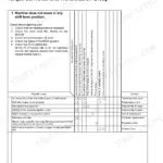
To address starting and idle problems on the Kawasaki Brute Force 650, consult the "Troubleshooting Guide" on page 500. Starting difficulties can be caused by a low battery voltage, a blown fuse, or a faulty starter motor clutch. Poor running at low speed might be caused by a weak spark due to a dirty spark plug or an incorrect fuel/air mixture, such as a maladjusted pilot screw or a clogged air cleaner. p. 500
What are the replacement specifications for CVT drive belt (P/N 99924-1261-04)?
The manual does not list replacement specifications for a CVT drive belt with part number 99924-1261-04. However, for the drive belt in general, the service limit for belt deflection is 28.0 mm (1.102 in.), and for belt height (parallel portion) it is 0.64 mm (0.0252 in.), as specified on page 168. p. 168
Is this Kawasaki Brute Force 650 4x4 & variants manual a digital download?
This is a 528-page searchable PDF ready for immediate download. Works on any device, so pull it up on your phone while you're under the hood. No shipping, no waiting.
Can I print pages of this Kawasaki Brute Force 650 4x4 for my own shop?
Yes. Print a chapter or just the pages for the job at hand, for use in your own shop. Any home or office printer works.
Reviews
There are no reviews yet.