
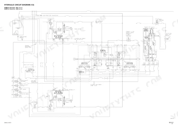
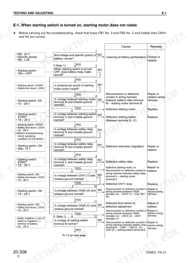
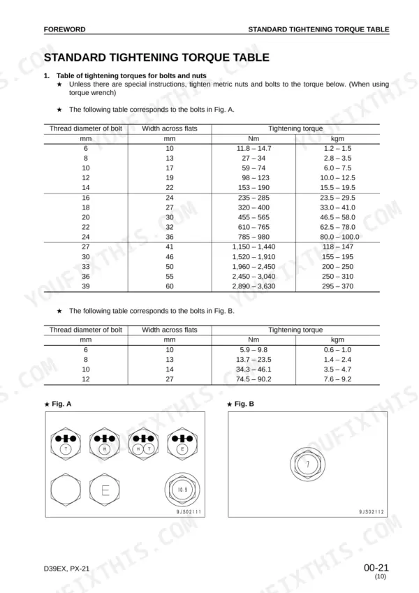
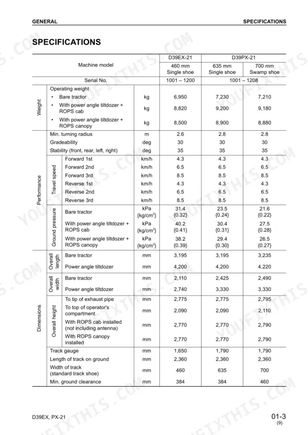
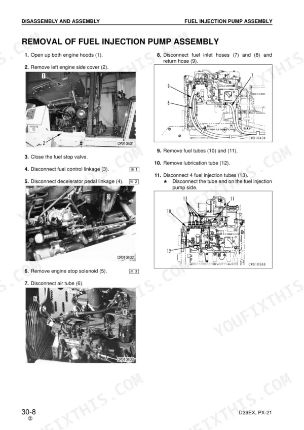
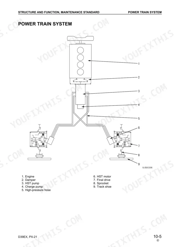
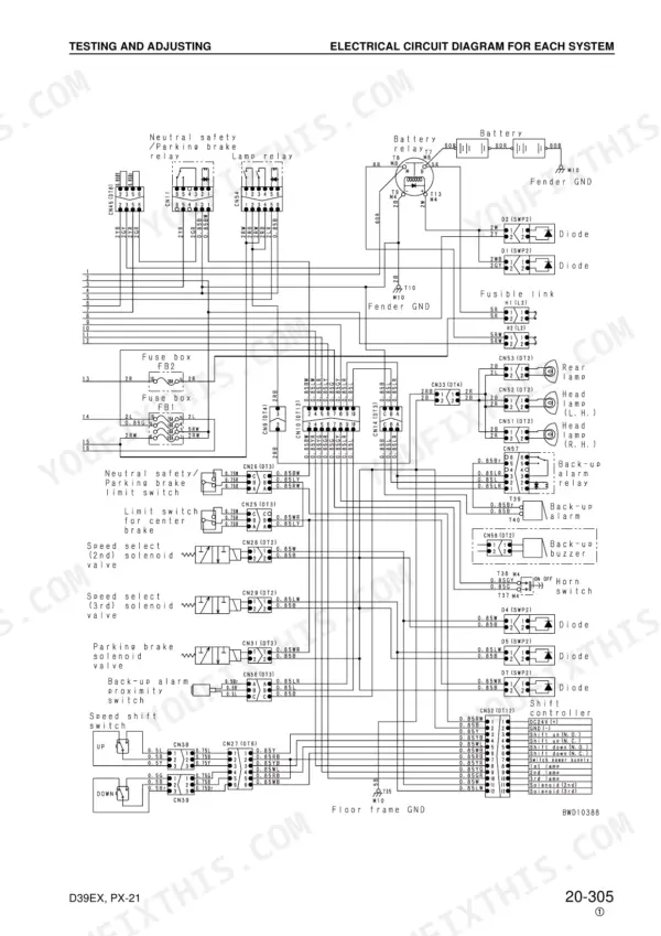
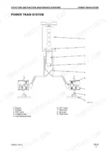
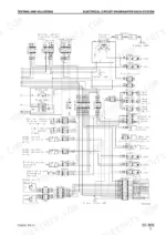
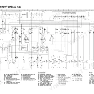
Whether you are checking HST oil pressure this afternoon or splitting a final drive, the Komatsu D39EX-21, D39PX-21 shop manual PDF (Komatsu SEBM023810, 464 pages) puts the factory procedures for both bulldozer variants on the bench beside you. Troubleshooting fills roughly a third of the book. It is split into electrical, hydraulic and mechanical, machine monitor, and engine sections that take each fault from symptom to failed component. Full hydraulic and electrical circuit diagrams close out the manual, so you can trace PPC lines and the HST loop from pump to travel motor, and standard value tables give you blow-by, relief pressure, and valve clearance targets. When bleeding a work equipment cylinder, stop it 100 mm short of stroke end for the first 4 to 5 cycles; Nominal No. 03 and 04 O-ring boss joints take 84 to 132 Nm. Blade drift rarely announces its own cause. Your bookmarked, text-searchable copy goes wherever the dozer is parked.
What's Inside This Komatsu D39EX-21, D39PX-21 Manual
| System | Pages | Key Topics |
|---|---|---|
| General | 35-43 | Specification Drawing, Specifications, Weight Table |
| Structure and Function, Maintenance Standard | 44-171 | Cooling System, HST Pump, HST Motor, Control Valve |
| Standard Value Tables | 172-180 | Engine Standard Values, Chassis Standard Values, Electrical System Standard Values |
| Testing and Adjusting Procedures (Engine) | 181-197 | Engine Speed, Exhaust Color, Blow-By Pressure, Valve Clearance, Fuel Injection Timing, Compression Pressure |
| Testing and Adjusting Procedures (Chassis) | 198-225 | Air Conditioner Compressor Belt, HST Oil Pressure, Solenoid Valve Output Pressure, Work Equipment Main Relief Pressure, PPC Valve Output Pressure, Parking Brake Release |
| Troubleshooting (General and Electrical) | 226-312 | Troubleshooting Points, Electrical System Troubleshooting, Starting Motor, Headlamp, Air Conditioner, Backup Alarm, Horn |
| Troubleshooting (Hydraulic and Mechanical) | 313-329 | Travel System, Work Equipment, Hydraulic Drift, HST Noise, Engine Stalls |
| Troubleshooting (Machine Monitor System) | 330-347 | Monitor Panel, Preheating Caution Lamp, HST Oil Temperature Gauge, Engine Water Temperature Gauge, Fuel Level Gauge, Service Meter |
| Troubleshooting (Engine System) | 348-371 | Starting Performance, Engine Rotation, Exhaust Smoke, Oil Consumption, Coolant Temperature, Abnormal Noise, Vibration |
| Disassembly and Assembly | 372-457 | Fuel Injection Pump Assembly, Cylinder Head Assembly, Travel Motor and Final Drive Assembly, Main Control Valve Assembly |
| Others | 458-464 | Hydraulic Circuit Diagram, Electrical Circuit Diagram |
Quick Reference Specifications
| Specification | Value | Page |
|---|---|---|
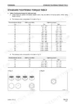
| Tightening torque for O-ring boss piping joints (Nominal No. 02) | 35 – 63 Nm | p. 22 |
| Tightening torque for O-ring boss piping joints (Nominal No. 03, 04) | 84 – 132 Nm | p. 26 |
| Tightening torque for 102, 107 and 114 engine series (Taper screws 1/16 inch) | 3 ± 1 Nm | p. 28 |
| Tightening torque for 102, 107 and 114 engine series (Taper screws 1/8 inch) | 8 ± 2 Nm | p. 28 |
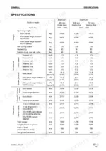
| Engine oil pan capacity (Specified) | 14 L | p. 43 |
| Engine oil pan capacity (Refill) | 12.5 L | p. 43 |
| Alternator voltage | 27.5–29.5V | p. 180 |
| Oil pressure gauge range | 1 MPa {10 kg/cm2} | p. 194 |
| Final drive case oil capacity | 3.91 L | p. 409 |
| Mounting bolt torque | 98 – 123 Nm | p. 408 |
Komatsu D39EX-21, D39PX-21 Common Problems This Manual Covers
Komatsu D39EX-21 and D39PX-21 starting motor will not turn or engine shows poor starting performance
Test the starting motor circuit with the E-mode electrical troubleshooting before condemning the motor, and check the engine stop solenoid circuit in the same section. If the engine cranks but is slow to fire, work through the S-mode starting performance and engine rotation checks beginning on page 348.
Manual Section: Troubleshooting for Engine System (S-MODE) p. 348HST travel speed slow, steering response poor, or abnormal noise coming from the HST pump
Measure HST oil pressure with the chassis testing procedure starting on page 198 before you pull a pump or motor. Run the H-mode travel and steering troubleshooting from page 313 to separate an HST pump fault from an HST motor or control valve fault. Check solenoid valve output pressure in the same chassis tests.
Manual Section: Troubleshooting for Hydraulic and Mechanical System (H-MODE) p. 313Work equipment shows hydraulic drift, slow operating speed, or weak power at the hydraulic cylinders
Test work equipment main relief pressure and PPC valve output pressure using the chassis procedures beginning on page 198. Work through the H-mode hydraulic drift checks on page 313. After cylinder work, bleed air per page 20: cycle each cylinder 4 to 5 times, stopping 100 mm short of stroke end, then 3 to 4 times to full stroke.
Manual Section: Troubleshooting for Hydraulic and Mechanical System (H-MODE) p. 313Engine oil pressure drops low or oil consumption is higher than normal between services
Check engine oil level first; pan capacity is 14 L specified and 12.5 L at refill per page 43. Then verify actual pressure with a gauge rated to 1 MPa {10 kg/cm2} following the engine testing procedure on page 194. If pressure stays low, run the S-mode oil pressure and oil consumption checks from page 348.
Manual Section: Troubleshooting for Engine System (S-MODE) p. 348Engine water temperature gauge reads high and coolant temperature keeps rising during operation
Verify the gauge itself first with the M-mode engine water temperature gauge checks starting on page 330, because a bad reading sends people chasing the wrong fault. If the gauge checks out, run the S-mode coolant temperature troubleshooting from page 348. After repairs, fill the cooling system to its 32 L capacity, including the sub-tank, per page 43.
Manual Section: Troubleshooting for Engine System (S-MODE) p. 348Engine output feels low and exhaust smoke color looks abnormal during operation
Measure exhaust color, blow-by pressure, and compression pressure using the engine testing procedures starting on page 181 before touching the fuel injection pump. Check fuel injection timing and valve clearance next. If you pull a nozzle holder assembly, torque it to 60 ± 9 Nm {6.12 ± 0.92 kgm} on reinstall per page 192.
Manual Section: Testing and Adjusting Procedures (Engine) p. 181Frequently Asked Questions
How do I troubleshoot a D39EX-21 or D39PX-21 that will not start?
If the starting motor does not rotate, first check that the battery voltage and specific gravity are normal. Then, verify the starting switch, battery relay, and safety relay circuits. Detailed troubleshooting steps for this condition are provided on page 289, with the related electrical circuit diagram on page 290. p. 289
What are the replacement specs for the HST charge filter element on the Komatsu D39EX-21, D39PX-21?
The HST charge filter element should be replaced if it is clogged. The cracking pressure for the filter is 103 ± 29.4 kPa {1.05 ± 0.3 kg/cm²}, and it has a filtering precision of 10 µm. p. 124
What is the tightening torque for the cylinder head mounting bolts on the Komatsu D39EX-21, D39PX-21?
The cylinder head mounting bolts must be tightened in three stages. The first stage is 90 ± 5 Nm {9.18 ± 0.51 kgm}, the second stage is 120 ± 5 Nm {12.24 ± 0.51 kgm}, and the final stage is an additional 90 ± 5° turn. p. 391
What is the standard valve clearance for the engine on the Komatsu D39EX-21, D39PX-21?
The standard valve clearance for the intake valve is 0.25 mm, and for the exhaust valve, it is 0.51 mm. p. 190
What is the hydraulic tank capacity on the Komatsu D39EX-21, D39PX-21?
The hydraulic tank capacity is 66.4 liters. p. 124
Is this Komatsu D39EX-21 manual a download or a disc?
Delivery is instant: a 464-page searchable PDF is yours the second checkout clears. Laptop, tablet, or phone, all fine.
Am I free to print this Komatsu D39EX-21 Shop Manual?
Yes. Print the sections you need to take out to the shop for your own use. Standard letter or A4 paper works.


Reviews
There are no reviews yet.