
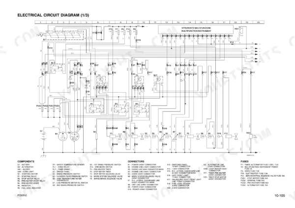
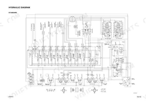
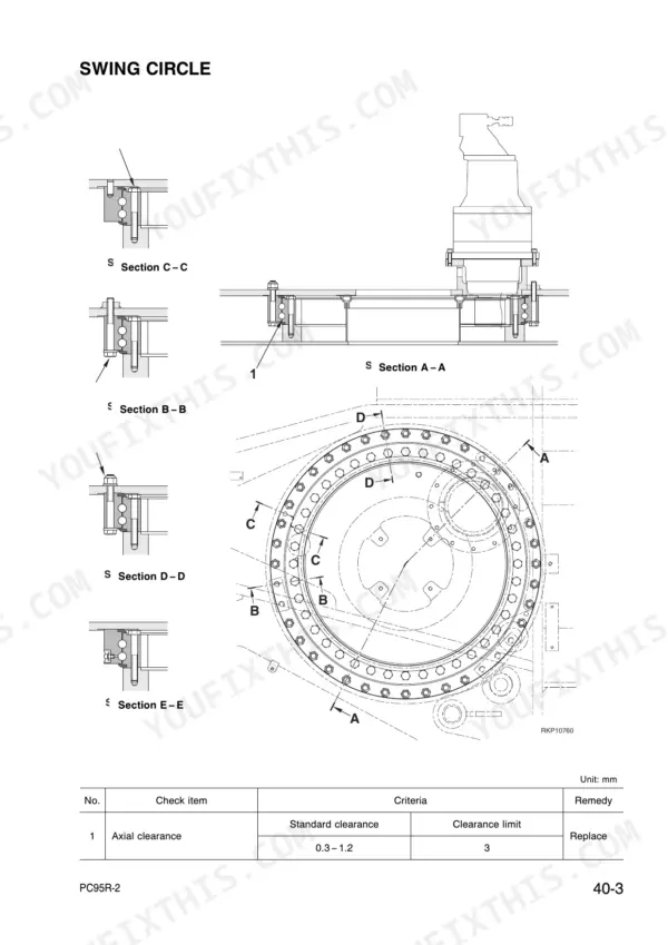
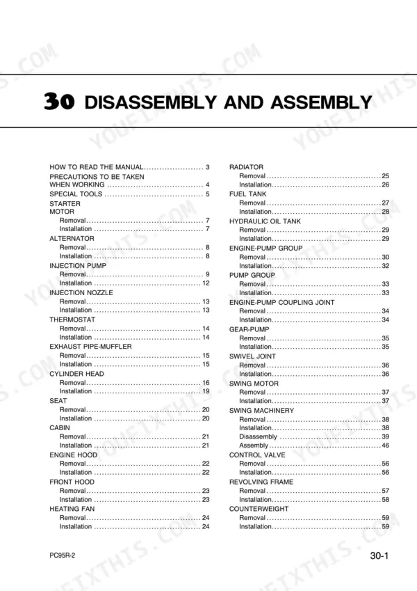
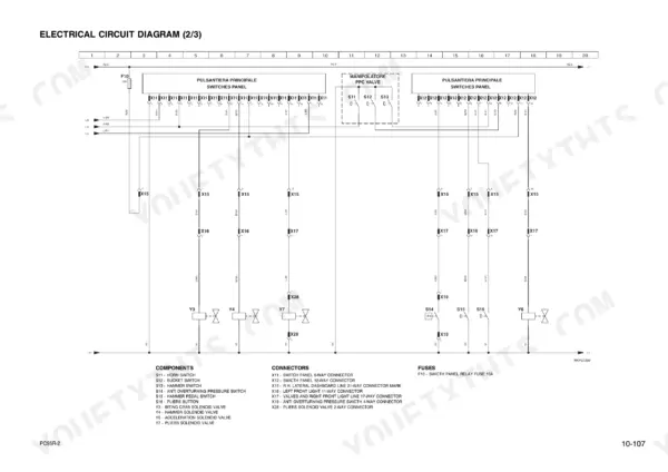
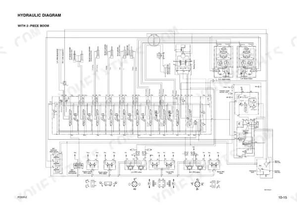
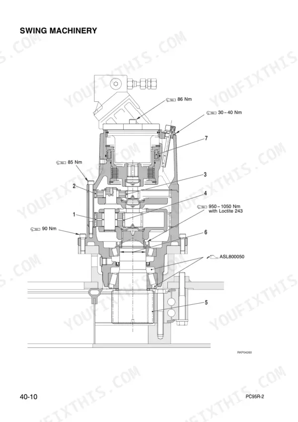
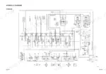
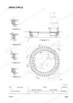
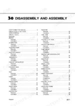
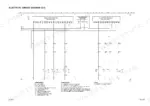
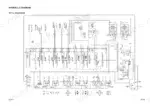
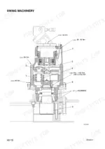
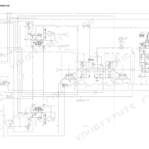
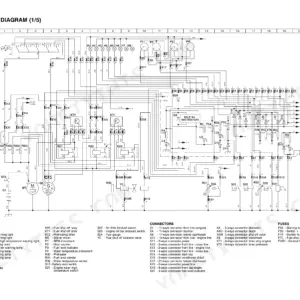
Setting track tension, checking pump pressure, or pulling a boom cylinder on a PC95R-2 hydraulic excavator this morning goes quicker with this 328-page Komatsu PC95R-2 shop manual PDF open beside you. Wiring diagrams trace the electrical circuits, and hydraulic schematics follow oil from the pump group through the control valve to the boom, arm, bucket, and blade cylinders. Removal and installation takes up most of the book, from the injection pump and swing motor to the final drive, idler, and recoil spring, while Testing and Adjusting covers engine speed, compression, and injection timing. Hold track-shoe tension to 20 to 25 mm between track roller and shoe, and check that P1 and P2 safety pressure reads 324 ± 4.9 bar. A wrong guess costs you the part, a second teardown, and a crew standing idle. With section bookmarks and a text layer you can search, the PDF takes you straight to the page that gets the machine digging again.
What's Inside This Komatsu PC95R-2 Manual
| System | Pages | Key Topics |
|---|---|---|
| Structure and Function | 17-28 | Track Frame, Swing Machinery |
| Maintenance Standard | 29-68 | Track Frame, Idler, Carrier Roller |
| Testing and Adjusting | 69-126 | Engine Speed, Compression Pressure, Fuel Injection Timing |
| General Procedures and Engine Components | 127-141 | Manual Reading, Special Tools, Starter Motor, Alternator, Injection Pump, Injection Nozzle |
| Engine Cooling and Exhaust Systems | 142-152 | Thermostat, Exhaust Pipe, Muffler, Cylinder Head, Radiator |
| Fuel and Hydraulic Tank Systems | 153-159 | Fuel Tank, Hydraulic Oil Tank, Pump Group |
| Engine-Pump Coupling and Swing Machinery | 160-182 | Engine-Pump Coupling Joint, Gear-Pump, Swing Motor, Swing Machinery, Control Valve |
| Revolving Frame and Counterweight | 183-185 | Revolving Frame, Counterweight |
| Undercarriage and Swing Circle | 186-194 | Swing Circle, Track Shoes, Sprocket Assembly, Final Drive, Idler, Recoil Spring, Track Roller, Carrier Roller |
| Control Valves and Pedals | 195-201 | R.H. PPC Valve, L.H. PPC Valve, Blade PPC Valve, Travel Pedal Control, 1st Boom Swing Pedal Control |
| Work Equipment Cylinders and Components | 202-328 | Boom Cylinder, 2nd Boom Cylinder, Arm Cylinder, Bucket Cylinder, Boom Swing Cylinder, Blade Cylinder, Swing Bracket, Blade |
Quick Reference Specifications
| Specification | Value | Page |
|---|---|---|
| Standard tightening torque for bolts and nuts (Thread diameter 6mm, Pitch 1mm, Width across flat 10mm, 8.8 grade) | 9.5 ± 1 Nm | p. 10 |
| Standard tightening torque for bolts and nuts (Thread diameter 6mm, Pitch 1mm, Width across flat 10mm, 10.9 grade) | 13.5 ± 1.5 Nm | p. 10 |
| P1 pump (Safety) pressure | 324 ± 4.9 bar | p. 72 |
| P2 pump (Safety) pressure | 324 ± 4.9 bar | p. 72 |
| Track-shoe tension (distance between track roller and track-shoe) | 20 - 25 mm | p. 96 |
| Fan belt deflection (used belt) | 10 - 15 mm | p. 91 |
| Fan belt deflection (new belt) | 7 - 9 mm | p. 91 |
| Cabin weight | 250 kg | p. 147 |
| Engine hood weight | 36 kg | p. 148 |
| Engine Speed (High Idling) | 2400 ± 25 rpm | p. 86 |
| Engine Speed (Low Idling) | 1100 ± 25 rpm | p. 86 |
| Compression Pressure (Normal) | 35 ± 1 kg/cm² | p. 70 |
Komatsu PC95R-2 Common Problems This Manual Covers
Komatsu PC95R-2 engine high idle and low idle speeds reading out of spec on the tachometer
Measure low idle and high idle speed against 1100 ± 25 rpm and 2400 ± 25 rpm, measured per page 86. If the speeds are right but the engine still pulls weak, check compression against 35 ± 1 kg/cm² and verify injection timing sits at 13° to 15° B.T.D.C. before you tear into anything else.
Manual Section: Testing and Adjusting p. 86Main relief pressure reading low at the gauge, boom and arm weak under load
Test main relief pressure following page 102. Section 1 should read 324 bar. On Section 2, check for 216 bar at port M2 on the blade, then 190 bar while swinging both directions with the blade grounded. After adjusting, torque the main valve locking nut to 49 to 59 Nm per page 103.
Manual Section: Testing and Adjusting p. 102Boom, arm, bucket or blade drifting down with the control levers in neutral
Check which function is drifting before you pull anything apart. Boom, arm, bucket, swing motor and blade each have their own cause list in the Analysis of the Causes of Hydraulic Drifts section on page 119. Work the matching list in order, note how far the attachment settles with the levers in neutral, and confirm each cause before you replace parts.
Manual Section: Hydraulic Drift Analysis p. 119Track-shoe tension too loose, track sagging excessively between the track roller and shoe
Measure dimension A between the track roller and the track-shoe following page 96. It should fall between 20 and 25 mm. Adjust tension until you land in that window, then walk the shoes and torque any loose track shoe bolts to 160 ± 10 Nm, the value given on page 36.
Manual Section: Track-Shoe Tension p. 96Fan belt loose with too much deflection under finger pressure on the belt span
Measure fan belt deflection under about 10 kg of finger force following page 91. A used belt should give 10 to 15 mm and a new one 7 to 9 mm. Adjust tension, then torque alternator mounting bolt (3) to 44.1 to 53.9 Nm and bolt (4) to 22.5 to 28.4 Nm.
Manual Section: Fan Belt Tension p. 91Hydraulic pump, cylinders, swing motor and travel motors running with trapped air after hydraulic service
Remove the P1 pump air bleed plug following page 97 to bleed the pump, then reinstall it at 17.2 ± 2.5 Nm. Bleed the cylinders, swing motor and travel motors in the same pass before you load the machine. Check tank level afterward and top up. Total hydraulic oil quantity is 74 L per page 151.
Manual Section: Hydraulic Circuit Air Bleeding p. 97Frequently Asked Questions
How do I bleed the air from the hydraulic system on the Komatsu PC95R-2?
Air bleeding is required after replacing hydraulic components. For the main pump P1, loosen the air bleed plug (1) on the pump body (2), fill the tank until the level reaches the hole, tighten the plug, and run the engine at low idling for 10 minutes. For hydraulic cylinders, run the engine at low idling for 5 minutes, then raise and lower the boom 4-5 times, operating the piston rod to approximately 100 mm before the end of its stroke. p. 97
What is the standard torque for the cylinder head bolts on the Komatsu PC95R-2?
The cylinder head bolts must be tightened in two stages. The first tightening is 88.3 - 98.1 Nm (9 - 10 kgm), and the final tightening is 181.4 - 191.2 Nm (18.5 - 19.5 kgm). p. 35
What is the standard valve clearance for the intake and exhaust valves on the Komatsu PC95R-2 engine?
At a cold engine state, the standard clearance for both the intake and exhaust valves is 0.30 ± 0.05 mm. p. 87
What is the required coolant capacity for the Komatsu PC95R-2 engine cooling system?
The engine cooling system requires approximately 18 liters of coolant liquid. p. 140
What is the standard deflection for the fan belt on the Komatsu PC95R-2?
The fan belt tension should be checked by pushing the belt at the midway point between the alternator and the water pump pulley. The deflection should be 10 - 15 mm with a pressure of 10 kg (98 N). p. 91
How is this Komatsu PC95R-2 Shop Manual delivered?
Delivery is instant: a 328-page searchable PDF is yours the second checkout clears. Laptop, tablet, or phone, all fine.
Am I able to print pages from this Komatsu PC95R-2 manual?
Yes. Print a single page or a chapter for your own shop use, on letter or A4.


Reviews
There are no reviews yet.