
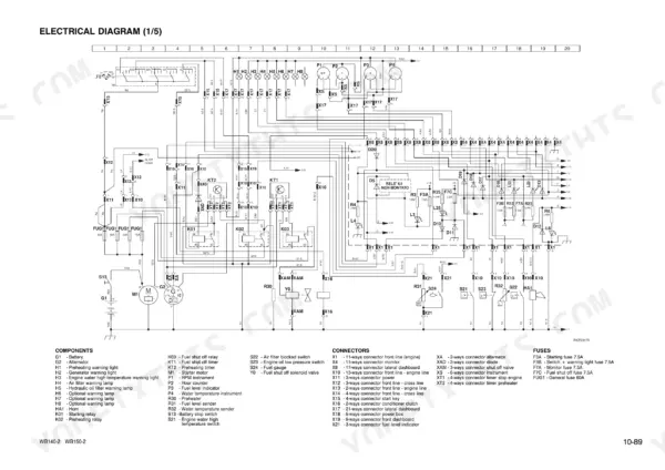
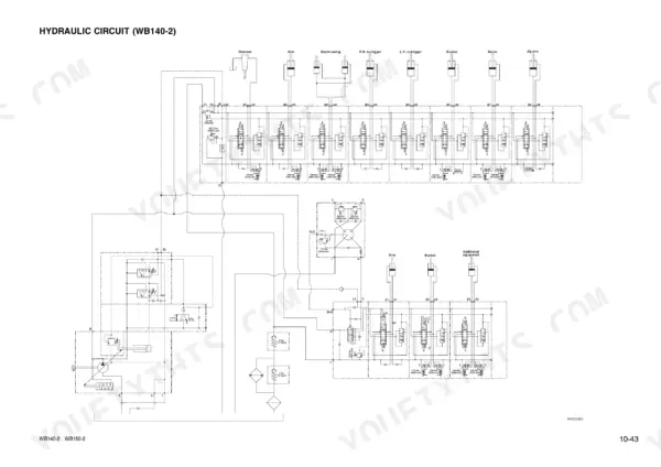
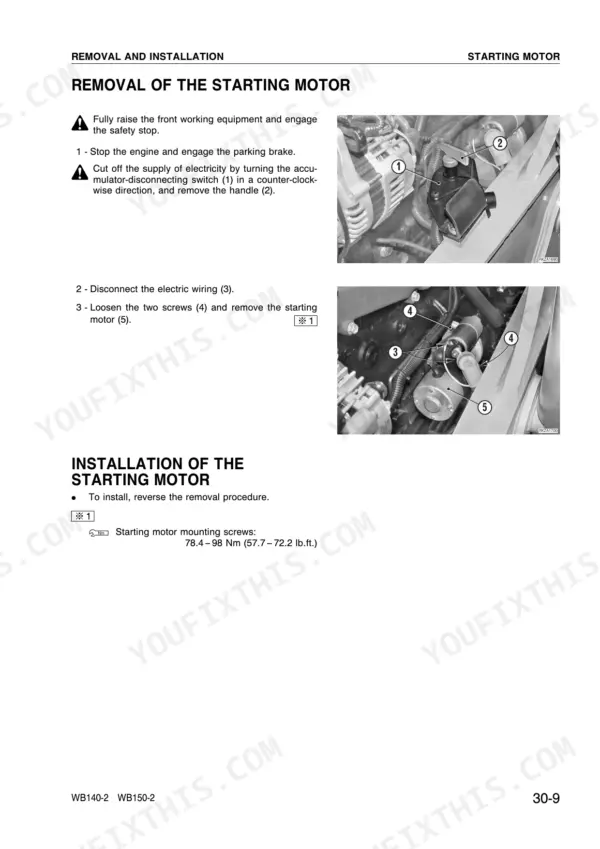
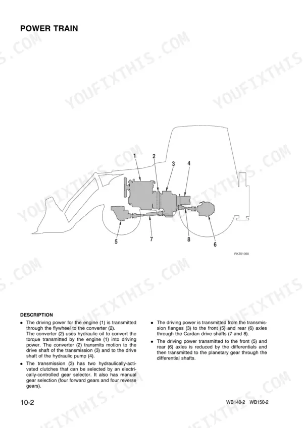
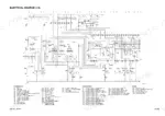
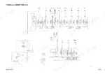
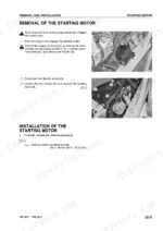
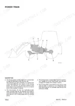
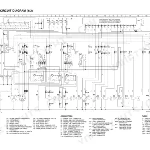
Getting a WB140-2 or WB150-2 backhoe loader through a transmission overhaul right the first time is what you buy with the 509 pages of this Komatsu WB140-2, WB150-2 shop manual PDF, publication WEBM001102. Wiring diagrams trace the electrical circuits, hydraulic schematics map oil flow from the pump through the control valve block, and nearly a fifth of the book explains how the power train works before you pull a bolt. Disassembly and assembly fills more than half the manual: starting motor, injection pump, transmission dismantling, front and rear axles, final drives and the backhoe and loader cylinders, backed by Testing and Adjusting checks and Maintenance Standard wear limits. Set the max pressure valve at 23 bar (333.6 psi) and run 8 mm grade 8.8 bolts to 23 ± 2 Nm. A wrong guess on clutch clearance costs you a second teardown. Search the text, jump between bookmarked sections, and have that WB150-2 back on the job sooner.
What's Inside This Komatsu WB140-2, WB150-2 Manual
| System | Pages | Key Topics |
|---|---|---|
| Structure and Function | 18-103 | Power Train, Control Valve Block, Hydraulic Pump |
| Testing and Adjusting | 104-174 | Engine Speed, Hydraulic Drift |
| General Information and Special Tools | 175-181 | Manual Reading, Safety Precautions, Special Tools List |
| Engine and Power Train Components | 182-231 | Starting Motor, Alternator, Injection Pump, Transmission Removal and Installation |
| Transmission Overhaul | 232-275 | Transmission Dismantling, Input Shaft, Secondary Shaft, Clutch Function Testing |
| Axle and Final Drive Components | 276-384 | Boom Swing Cylinder, Front Axle Disassembly, Rear Axle Final Drive, Differential Locking |
| Hydraulic Cylinders and Working Equipment | 385-468 | Differential Lock Assembly, Backhoe Boom Cylinder, Front Bucket Tilt Cylinders, Backhoe Working Equipment |
| Maintenance Standard | 469-509 | Transmission, Front Axle, Brakes |
Quick Reference Specifications
| Specification | Value | Page |
|---|---|---|
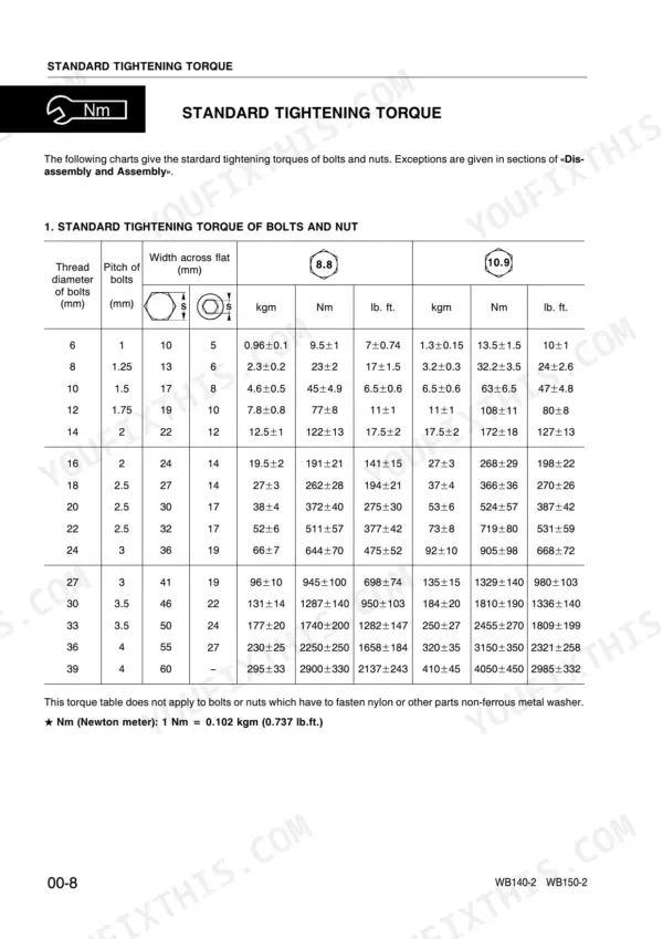
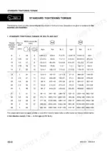
| Standard Tightening Torque (6mm bolt, 8.8 grade) | 9.5 ± 1 Nm | p. 8 |
| Standard Tightening Torque (8mm bolt, 8.8 grade) | 23 ± 2 Nm | p. 8 |
| Standard Tightening Torque (6mm bolt, 10.9 grade) | 13.5 ± 1.5 Nm | p. 8 |
| Standard Tightening Torque (8mm bolt, 10.9 grade) | 32.2 ± 3.5 Nm | p. 8 |
| Max. pressure valve | 23 bar (333.6 psi) | p. 22 |
| Front shovel control valve nominal pressure | 206 ± 8 bar (2987 ± 116 psi) | p. 149 |
| Standard tightening torque for 6mm bolt (8.8) | 9.5 ± 1 Nm | p. 10 |
| Standard tightening torque for 24mm bolt (10.9) | 905 ± 98 Nm | p. 10 |
| Engine oil pan capacity (WB140-2 Aspirated) | 8.6 L | p. 15 |
| Engine oil pan capacity (WB140-2 Turbocharged) | 7.9 L | p. 15 |
| Hydraulic system capacity | 150 L | p. 15 |
| Fuel tank capacity | 130 L | p. 15 |
Komatsu WB140-2, WB150-2 Common Problems This Manual Covers
Komatsu WB140-2 and WB150-2 front equipment and backhoe showing hydraulic drift when held raised
Check drift on the front equipment and backhoe separately with a loaded bucket, timing how far each function creeps. Then work through the Analysis of Causes of Hydraulic Drift section on page 167 before you pull a cylinder or control valve block. Confirm which side is leaking down so you rebuild the right part, not the expensive guess.
Manual Section: Hydraulic Drift Analysis p. 167Front shovel and backhoe functions weak with control valve pressure testing below nominal
Measure control valve pressure with a gauge at operating temperature and compare it against the figures on page 149. On a WB140-2, the front shovel valve should hold 206 ± 8 bar (2987 ± 116 psi) and the backhoe valve 228 ± 8 bar (3306 ± 116 psi). If both read low, inspect hydraulic pump PC valve and LS valve operation.
Manual Section: Testing and Adjusting p. 149After input and secondary shaft rebuild, transmission clutches failing the clutch function test
Check the power train max pressure valve calibration first; page 22 lists 23 bar (333.6 psi). If pressure is right, dismantle the transmission following page 232, inspect the input shaft and secondary shaft assemblies, and reassemble to the overhaul sequence. Repeat the clutch function testing before you reinstall the transmission in the machine.
Manual Section: Transmission Overhaul p. 232Rear axle differential lock selected from the operator seat but not engaging or releasing
Check the differential locking circuit at the control valve block first, since that is where the lock is controlled. If the hydraulics check out, remove the rear axle final drive and differential following page 276, then inspect the differential lock assembly for wear or damage before reassembly.
Manual Section: Axle and Final Drive Components p. 276During tappet check, engine speed reading out of specification and valve clearance out of adjustment
Measure engine speed first, then adjust valve clearance following page 135. Torque the tappet nut to 14.7 to 19.6 Nm (10.8 to 14.4 lb.ft.) and the valve cover lock nut to 25 ± 3 Nm (18.4 ± 2.2 lb.ft.). Recheck engine speed after closing up to confirm the adjustment held.
Manual Section: Engine Speed Tests p. 135Frequently Asked Questions
What are the hydraulic relief-pressure settings for the WB140-2 and WB150-2?
The main relief pressure for the 6-7-8 spool control valve is 207 bar (3001.5 psi) for the WB140-2 and 220 bar (3190 psi) for the WB150-2. Secondary valve settings for the boom raising circuit are 350 bar (5075 psi) for both models. p. 112
What are the cylinder head bolt torque specs for the Komatsu WB140-2, WB150-2 backhoe loader?
The cylinder head bolts must be tightened in two stages. The first tightening is 88.3–98.1 Nm (65–72.3 lb.ft.), and the final tightening is 181.4–191.2 Nm (133.6–140.9 lb.ft.). p. 199
What is the correct valve clearance for the engine on the Komatsu WB140-2, WB150-2 backhoe loader?
For the 4D106-1FA and S4D106-1FH/1FA engines, the intake and exhaust valve clearance is 0.20 ± 0.05 mm (0.008 ± 0.002 in.) or 0.30 ± 0.05 mm (0.012 ± 0.002 in.) depending on the specific engine model. p. 135
What is the required fan belt tension for the engine?
The fan belt tension should be checked by applying a force of approximately 10 kg (22 lb.). The resulting deflection should be 10–15 mm (0.4–0.6 in.) for a used belt, or 7–9 mm (0.28–0.35 in.) for a new belt. p. 139
What is the engine oil capacity for the WB140-2 and WB150-2?
The engine oil pan takes 8.6 liters (2.27 US gal) on the WB140-2 aspirated engine, 7.9 liters (2.08 US gal) on the WB140-2 turbocharged engine, and 8.6 liters (2.27 US gal) on the WB150-2 turbocharged engine, the same for first fill and oil change (page 15). p. 15
How will I receive this Komatsu WB140-2 Shop Manual?
You download the Shop Manual yourself: 509 pages, searchable PDF, available immediately. Keep a copy on every device you use.
Does this Komatsu WB140-2 manual allow printing?
Yes. Print the pages you need for the job in your own shop, and bin them when they get greasy.


Reviews
There are no reviews yet.