
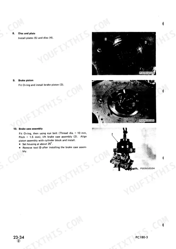
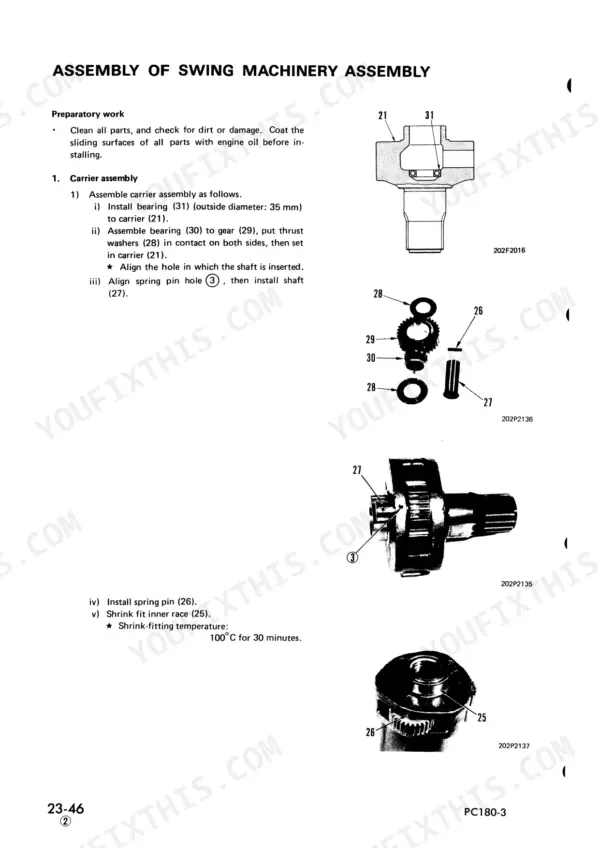
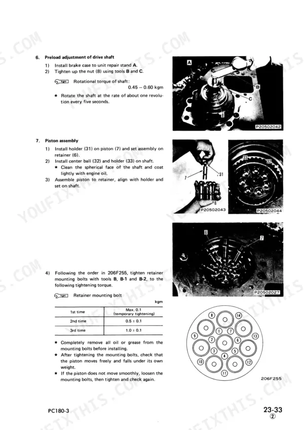
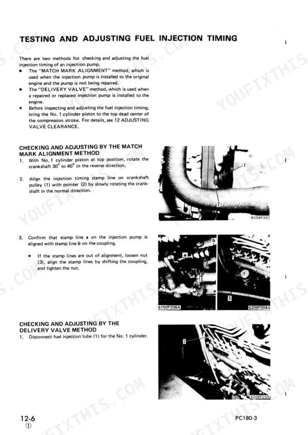

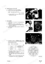
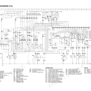
Komatsu shop manual SEBM021P0304 strips the PC180-3 series hydraulic excavator down system by system over 502 pages, covering six variants from the PC180LC-3 and PC180LLC-3 to the PC180NLC-3K. Hydraulics claim most of the book: the circuit diagram traces oil from the main pump, servo and TVC valves into the L.H. 6-spool and R.H. 5-spool control valves, and your boom, arm and bucket cylinders each get teardown and maintenance standards. Electrical wiring diagrams for the monitor system, plus final drive, travel motor, swing machinery and undercarriage rebuilds (idler, recoil spring, track rollers), round out the PDF. Set track tension to 60 to 100 mm of clearance, and warm the oil to 45 to 55°C before you fit a 600 kg/cm² gauge to the main relief. A slow arm means two valve banks to suspect. With bookmarks and a text layer, the manual rides in your service truck and searches by keyword beside the machine.
What's Inside This Komatsu PC180-3 Series Manual
| System | Pages | Key Topics |
|---|---|---|
| Engine | 11-66 | Structure and Function, Testing and Adjusting, Disassembly and Assembly |
| Power Train | 67-116 | Center Swivel Joint, Travel Motor, Final Drive, Swing Machinery |
| Undercarriage | 117-124 | Idler, Recoil Spring Assembly, Track Roller Assembly |
| Hydraulic System Outline and Tank | 125-130 | Work Equipment Piping, Hydraulic Circuit Diagram, Hydraulic Tank, Charging Pump |
| Hydraulic Pump Assembly | 131-171 | Main Pump, Servo Valve, TVC Valve, CO-NC Valve, Piston Pump |
| Control Valves | 172-212 | L.H. 6-Spool Control Valve, R.H. 5-Spool Control Valve, Solenoid Valve |
| Hydraulic Cylinders | 213-274 | Boom Cylinder, Arm Cylinder, Bucket Cylinder, Cushion Cylinder |
| Work Equipment Hydraulic Control | 275-328 | Work Equipment Piping, Boom Control, Arm Control, Bucket Control, PPC Valve, Accumulator |
| Testing and Adjusting Hydraulic Control | 329-402 | Relief Valve, Travel Motor Performance, Center Swivel Joint, Piston Pump Delivery, Troubleshooting |
| Hydraulic System Maintenance Standards | 403-414 | Control Valve, PPC Valve, Charging Pump, Work Equipment, Hydraulic Cylinder |
| Electrical System | 415-502 | Electric Vehicle Monitor System, Testing and Adjusting |
Quick Reference Specifications
| Specification | Value | Page |
|---|---|---|
| Machinery case oil capacity | Approx. 7 L | p. 106 |
| Track tension clearance | 60 - 100 mm | p. 121 |
| Hydraulic cylinder piston rod and bushing clearance (Boom cylinder) | 0.177 - 0.465 mm | p. 414 |
| Hydraulic cylinder piston rod and bushing clearance (Arm cylinder) | 0.161 - 0.445 mm | p. 414 |
| Oil temperature for relief pressure measurement | 45 - 55°C | p. 339 |
| Pressure gauge for main relief pressure measurement | 600 kg/cm² | p. 339 |
| Control lever at neutral pressure | 15.5 ± 1 kg/cm² | p. 384 |
| Control lever at neutral pressure (TVC valve) | Min. 18 kg/cm² | p. 386 |
| Engine Oil Pan Capacity (Specified) | 12.5L | p. 9 |
| Engine Oil Pan Capacity (Refill) | 10.5L | p. 9 |
| Hydraulic Tank Capacity (Specified) | 195L | p. 9 |
| Hydraulic Tank Capacity (Refill) | 134L | p. 9 |
Komatsu PC180-3 Series Common Problems This Manual Covers
Komatsu PC180LC-3 boom and arm cylinders show excessive hydraulic drift with control levers in neutral
Measure boom and arm hydraulic drift following page 392 and compare against the limits: boom max. 35 mm, arm max. 60 mm. If either one exceeds its limit, work through the Work Equipment troubleshooting charts to find out whether the cylinder or the control valve is at fault before you pull anything apart.
Manual Section: Work Equipment Troubleshooting p. 392Boom, arm and bucket operate at slow speed with weak work equipment response
Warm the hydraulic oil to 45 to 55°C, fit a 600 kg/cm² gauge and measure main relief pressure following page 339. Compare the reading against the 330 + 5 kg/cm² listed on page 388. If pressure reads low, adjust the relief valve and retest before you condemn the main pump.
Manual Section: Relief Valve Troubleshooting p. 339Engine speed drops below specification when one pump or both pumps are held at relief
Bring the hydraulic oil to 45 to 55°C, then relieve one pump and then two pumps while reading engine speed following chart H-6 on page 390. Speed must hold at min. 2200 rpm. If it sags below that, drain oil from the pump and look for metal particles: particles point to a failed pump, a clean drain points to the engine itself.
Manual Section: Testing and Adjusting Hydraulic Control p. 390PPC valve output pressure low with excessive time lag on work equipment controls
Warm the oil to 45 to 55°C and fit a 60 kg/cm² gauge to check charging pump circuit relief pressure following page 341. Then measure PPC valve output pressure against 30 ± 3 kg/cm² on page 388. If either reading falls short, inspect the charging pump and PPC valve before you touch the main pump.
Manual Section: Charging Pump Circuit Troubleshooting p. 341Track tension clearance out of specification on the idler and recoil spring assembly
Measure track tension clearance following page 121 and adjust until it sits within 60 to 100 mm. Inspect the idler, recoil spring assembly and track roller assembly while you are under the machine, then recheck clearance before returning it to work.
Manual Section: Undercarriage p. 121Boom, arm or bucket cylinder piston rod bushing worn with excessive rod clearance
Measure piston rod to bushing clearance and compare it with the standards on page 414: boom cylinder 0.177 to 0.465 mm, arm cylinder 0.161 to 0.445 mm, bucket cylinder 0.175 to 0.445 mm. While the cylinder is out, check rod bushing to pin clearance against the same table: 0.380 to 0.500 mm for boom and bucket, and 0.400 to 0.533 mm for arm.
Manual Section: Hydraulic System Maintenance Standards p. 414Frequently Asked Questions
What is the torque spec for the main pump input shaft housing mounting bolts on the Komatsu PC180-3 Series?
The mounting bolts for the main pump input shaft housing should be tightened to a torque of 1.4 ± 0.1 kgm. p. 132
What is the standard valve clearance for the S6D95L-1 engine in the Komatsu PC180-3 Series?
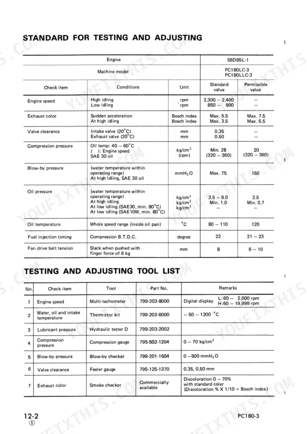
The standard valve clearance for the intake valve is 0.35 mm and for the exhaust valve is 0.50 mm, measured at 20°C. p. 22
What is the engine oil pan capacity for the Komatsu PC180-3 Series?
The engine oil pan has a specified capacity of 12.5 liters, with a refill capacity of 10.5 liters. p. 9
How do you adjust the fan belt tension on the PC180-3?
The fan belt tension is correct when the belt deflects 8 mm when pushed with a force of 6 kg at a point midway between the fan and alternator pulleys. Adjust by loosening the alternator mounting bolt and tension adjustment bolt, then using a bar to raise the alternator. p. 28
What is the torque spec for the cylinder head mounting bolts on the Komatsu PC180-3 Series excavator?
The cylinder head mounting bolts must be tightened in three steps: first to 8 kgm, second to 12 kgm, and finally to 15 kgm. p. 45
Is this Komatsu PC180 Series manual a download or a disc?
One searchable PDF covering 502 pages, delivered instantly. No disc, no shipping, no waiting on the post.
Can I print this Komatsu PC180 Series manual?
Yes. Print individual pages or full chapters for your own shop use, on letter or A4 paper.



Reviews
There are no reviews yet.