
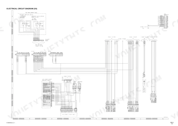
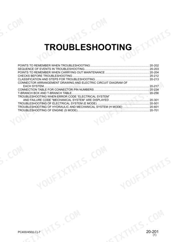
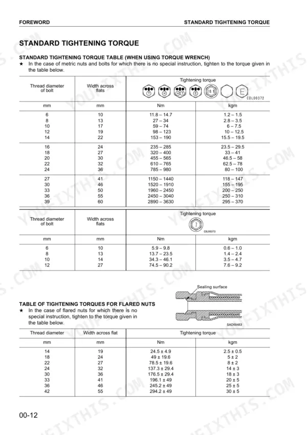
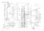
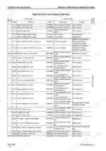
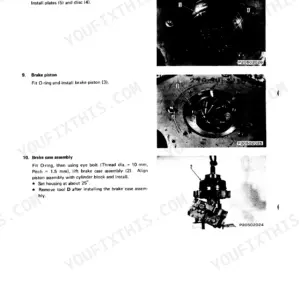
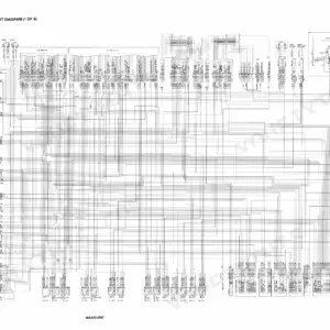
Electrical faults are the hardest calls on these machines, and the 782-page Komatsu PC400-7 shop manual PDF (OEM ID SEBM033007) gives them more room than any other chapter, tracing S-NET communication, engine controller and solenoid valve failures across four variants of the PC400-7 and PC450-7 hydraulic excavator family, standard and LC. Beyond that E mode section, the H mode and S mode charts trace hydraulic drift, slow swing, weak travel speed, overheating and hard starting back to a cause, and the disassembly chapter takes you through the cylinder head, swing motor and final drive. Wiring diagrams at the back show the full electrical circuit routing. Check No. 1 sun gear to planetary gear backlash at 0.15 to 0.54 mm, and torque 10 mm metric bolts to 59 to 74 Nm. Out on a remote site, there is nobody to call. Bookmarked chapters and a searchable text layer take you straight to the fix and get your excavator running under load again.
What's Inside This Komatsu PC400-7, PC400LC-7, PC450-7, PC450LC-7 Manual
| System | Pages | Key Topics |
|---|---|---|
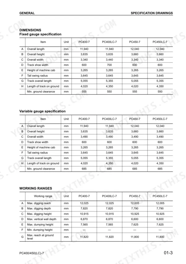
| General | 28-39 | Specification Drawings, Specifications, Weight Table |
| Structure, Function and Maintenance Standard | 40-238 | Hydraulic Pump, Control Valve, Swing Motor |
| Engine Testing and Adjusting | 239-289 | Engine Speed, Intake Air Pressure, Exhaust Gas Temperature, Valve Clearance, Compression Pressure, Engine Oil Pressure |
| Chassis Testing and Adjusting | 290-354 | Swing Brake Angle, Travel Speed, Hydraulic Drift, Work Equipment Speed, Internal Leakage, Compound Operation Performance |
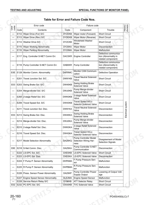
| Troubleshooting - Electrical System (E Mode) | 355-565 | Monitor Panel, Windshield Wiper, Engine Controller, S-NET Communication, Solenoid Valves, Air Conditioner System |
| Troubleshooting - Hydraulic and Mechanical System (H Mode) | 566-621 | Work Equipment Power, Swing Speed, Travel Speed, Hydraulic Drift, Abnormal Noise, Compound Operation |
| Troubleshooting - Engine (S Mode) | 622-644 | Starting Performance, Engine Stalling, Exhaust Smoke, Oil Consumption, Overheating, Abnormal Noise |
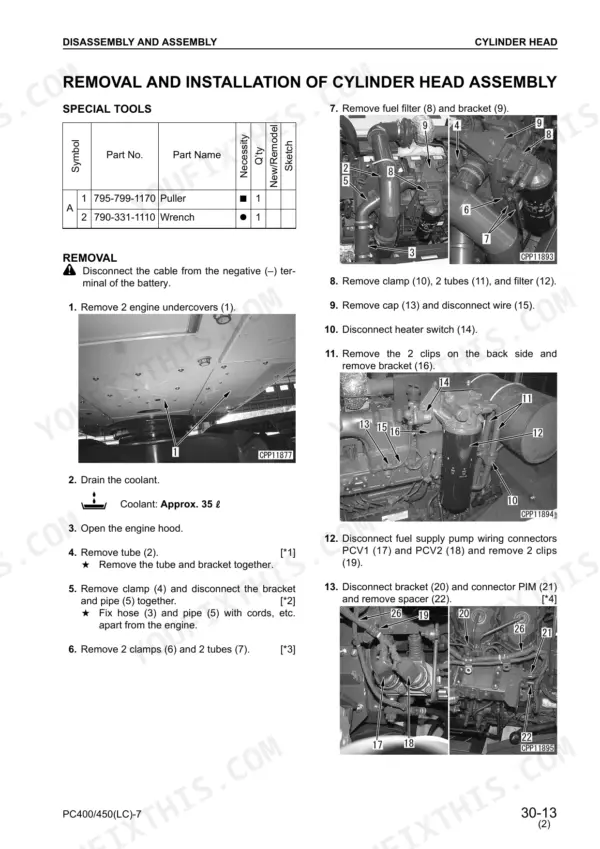
| Disassembly and Assembly | 645-771 | Removal and Installation of Cylinder Head Assembly, Disassembly and Assembly of Swing Motor and Swing Machinery Assembly, Disassembly and Assembly of Final Drive Assembly |
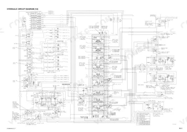
| Others | 772-782 | Hydraulic Circuit Diagram, Electrical Circuit Diagram |
Quick Reference Specifications
| Specification | Value | Page |
|---|---|---|
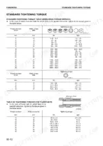
| Standard tightening torque for metric bolts (6mm) | 11.8 – 14.7 Nm | p. 662 |
| Standard tightening torque for metric bolts (8mm) | 27 – 34 Nm | p. 17 |
| Tightening torque for flared nuts (14mm) | 24.5 ± 4.9 Nm | p. 17 |
| Tightening torque for flared nuts (18mm) | 49 ± 19.6 Nm | p. 17 |
| Backlash between No. 1 sun gear and No. 1 planetary gear | 0.15-0.54 mm | p. 45 |
| Backlash between No. 1 planetary gear and ring gear | 0.18-0.66 mm | p. 45 |
| Backlash between swing motor shaft and No. 1 sun gear | 0.18-0.28 mm | p. 49 |
| Backlash between No. 1 planetary carrier and No. 2 sun gear | 0.40-0.75 mm | p. 49 |
| Hydraulic pump assembly tightening torque (Front pump pressure input) | 11.8-14.7 Nm | p. 662 |
| Hydraulic pump assembly tightening torque (Rear pump delivery pressure detection) | 11.8-14.7 Nm | p. 662 |
| Spool return spring (No. 11) Installed load | 416.5 N {42.5 kg} | p. 91 |
| Spool return spring (No. 11) Repair limit installed load | 333.2 N {34 kg} | p. 91 |
Komatsu PC400-7, PC400LC-7, PC450-7, PC450LC-7 Common Problems This Manual Covers
Komatsu PC400-7 swing speed slow and upper structure overruns past stopping point when swing lever released
Measure swing brake angle and swing speed using the Chassis Testing and Adjusting procedures starting on page 290. Check swing motor brake release pressure against 1.9 ± 0.4 MPa and safety valve set pressure against 27.9 MPa, both listed on page 107. Then work through the swing speed checks in H Mode troubleshooting from page 566.
Manual Section: Troubleshooting - Hydraulic and Mechanical System (H Mode) p. 566Swing pinion and swing circle show excessive backlash with clunk felt when swing reverses direction
Measure backlash between swing pinion and swing circle against 0.00 to 1.21 mm, and between swing motor shaft and No. 1 sun gear against 0.18 to 0.28 mm, following page 49. Check swing circle bearing axial clearance against 0.5 to 1.6 mm on page 50. Torque swing machinery mounting bolts to 824-1030 Nm (page 48).
Manual Section: Structure, Function and Maintenance Standard p. 49Boom, arm or bucket cylinder slowly drifts down under load while control levers sit in neutral
Measure hydraulic drift with the work equipment raised and measure cylinder internal leakage following the Chassis Testing and Adjusting procedures on page 290. Compare your readings against standard values, then run the hydraulic drift checks in H Mode troubleshooting from page 566 to pin down whether the leak is in the cylinder or the control valve.
Manual Section: Chassis Testing and Adjusting p. 290Bucket linkage pins and bushings knock with excessive play at arm, link and bucket joints
Measure pin to bushing clearance at the arm and bucket joint against 0.113 to 0.228 mm and at the link and bucket joint against 0.117 to 0.262 mm, following page 171. Check bucket clearance (a) against 0.5 to 1.0 mm. Then check the bucket cylinder rod support pin and bushing against 0.133 to 0.277 mm on page 169.
Manual Section: Structure, Function and Maintenance Standard p. 171Travel speed drops on one track side with growling noise from final drive case
Measure travel speed on both tracks following the Chassis Testing and Adjusting procedures on page 290. If one side runs slow or noisy, drain the final drive and check No. 1 sun gear to No. 1 planetary gear backlash against 0.15 to 0.54 mm on page 45. Torque the drain plug to 59-78 Nm (page 44) on refill.
Manual Section: Troubleshooting - Hydraulic and Mechanical System (H Mode) p. 566Engine produces heavy exhaust smoke, lacks power and overheats during digging under load
Measure engine speed, intake air pressure, exhaust gas temperature and compression pressure following Engine Testing and Adjusting from page 239. Compare every reading to standard values, then follow the S Mode exhaust smoke or overheating troubleshooting from page 622 to isolate the cause before you start pulling components off the engine.
Manual Section: Troubleshooting - Engine (S Mode) p. 622Frequently Asked Questions
How do I reset the maintenance interval on a Komatsu PC400-7 or PC450-7?
To reset the maintenance interval, select the maintenance item from the maintenance list display screen, press the input confirmation switch to enter the reset screen, and then press the input confirmation switch again to reset the time. After the reset is completed, the screen returns to the maintenance list display screen. p. 67
How do I clear electrical-system error records?
Only the abnormality record of the electrical system can be reset (deleted). While the electrical system abnormality record screen is displayed, operate the switches [ ] + [1] -> [2] -> [3] to display the reset screen, then follow the directions on the reset screen to perform the reset procedure. p. 146
What do Komatsu PC400-7 and PC450-7 error codes E955, E956, and E977 mean?
Error code E955 indicates an Engine S-NET error, E956 indicates an Engine power failure (1), and E977 indicates a Rail pressure sensor error. These codes are related to the engine controller system and require specific troubleshooting steps outlined in the manual. p. 153
How do I enter service mode on a PC400/450-7?
To enter the service menu, perform the following switch operation on the monitor panel: while holding the caution buzzer stop switch, hold the auto decelerator switch for 2.5 seconds. The initial screen of the service menu will then be displayed. p. 155
What is the standard tightening torque for the cylinder head mounting bolts on the Komatsu PC400-7?
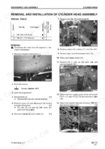
The cylinder head mounting bolts (1-6) must be tightened in three stages: first to 88.3 – 108 Nm (9 – 11 kgm), second to 157 – 167 Nm (16 – 17 kgm), and finally by retightening by 90° +30°/0°. p. 663
How will I receive this Komatsu PC400-7 Shop Manual?
Straight to your device: 782 pages of searchable Shop Manual, downloadable the moment payment goes through.
Can I print this Komatsu PC400-7 manual?
Yes. Print individual pages or full chapters for your own shop use, on letter or A4 paper.


Reviews
There are no reviews yet.