



This Kubota Workshop Manual covers the L185, L245, and L295 tractors, built around the Z751-A, DH1101-A, and D1301-A engines. It is the factory service document, publication 9Y011-10510, running 467 pages.
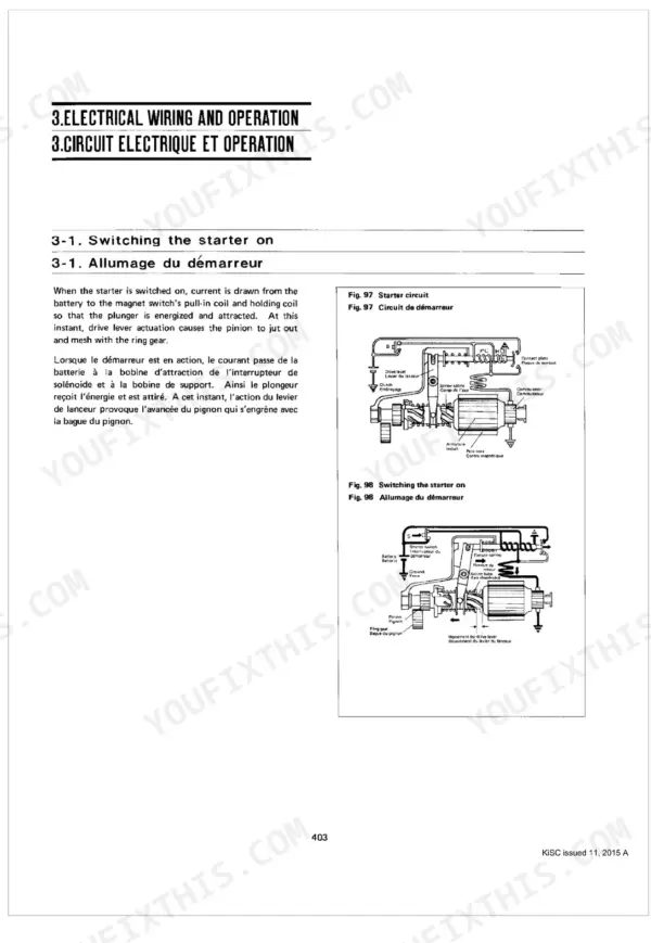
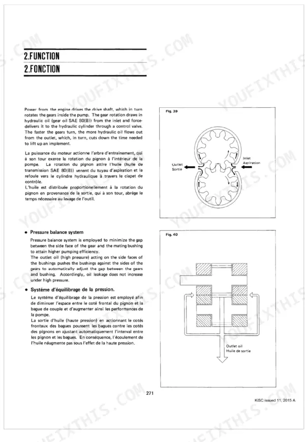
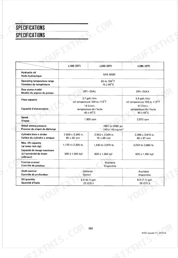
The manual is organized by system: preparatory disassembly steps, engine repair, the tractor body including clutch, steering, transmission, differential, and rear axle, the hydraulic power system, and the electrical system. It gives the construction and function of major components alongside disassembly and servicing procedures with reference values, such as clutch pedal free travel of 0.7874 to 1.1811 inch and a hydraulic relief setting of 1991 to 2062 psi.
This is the resource for owners and mechanics who want to handle clutch, brake, hydraulic, and engine work themselves rather than farm it out. It is delivered as a downloadable PDF you can search, print, and use on any device.
Complete the set for your L185, L245, L295
- Operator Manual: Kubota L245 Operator Manual
Other edition of this manual
What's Inside This Manual
| System | Pages | Key Topics |
|---|---|---|
| Symbol Reference Chart | 13-19 | Fasteners, Tools and Test Instruments, Standard Fasteners, Bolts, Screw, Nuts, Plugs, Washers, Cir-Clips |
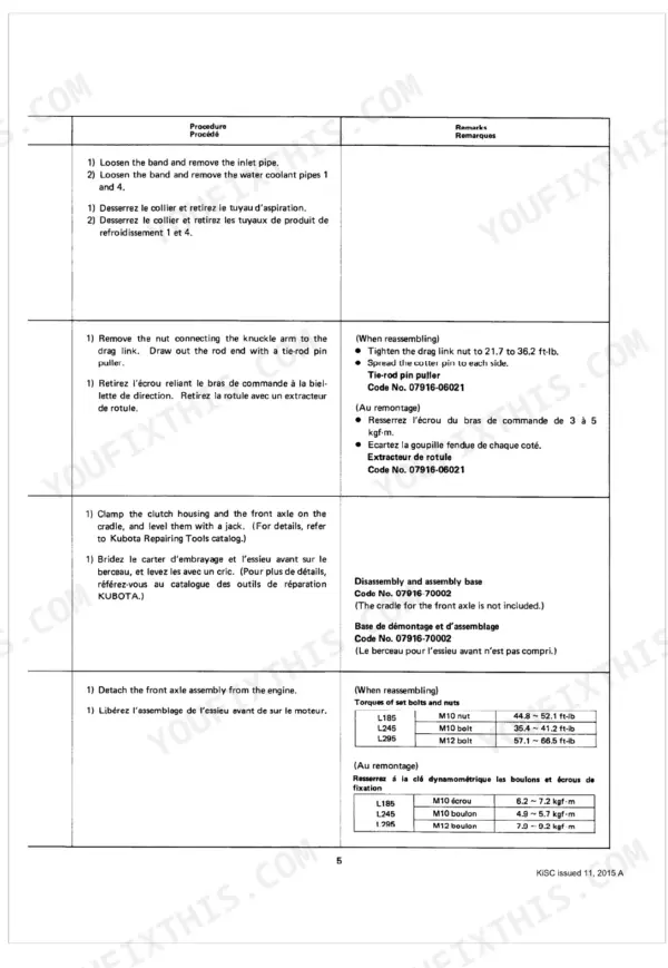
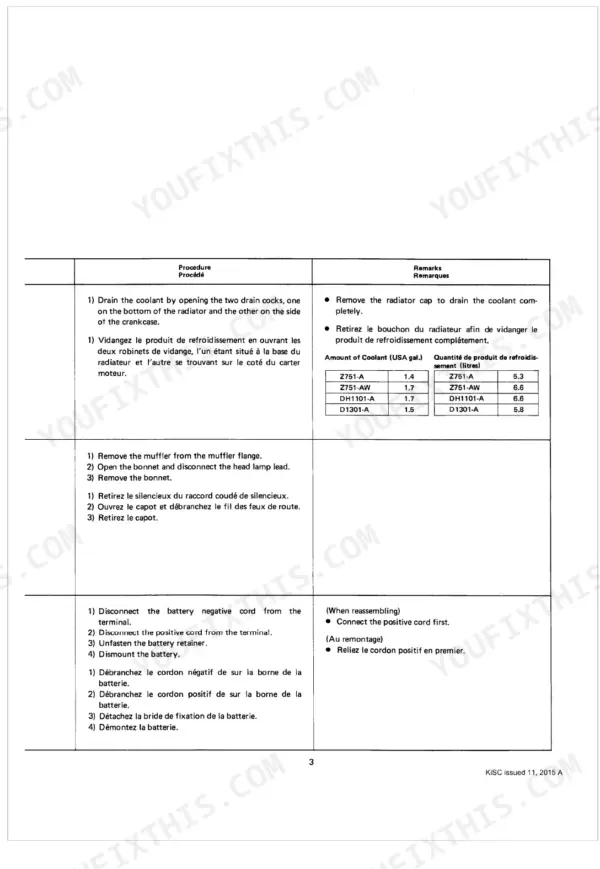
| Preparatory Steps for Disassembly and Servicing | 20-57 | Separation of Front Axle, 1-1 2-Wheel Drive, 2-Wheel Drive, Disassembly (1) Radiator Coolant, Disassembly (2) Bonnet, Muffler, Disassembly (3) Battery, Disassembly (4) Inlet Pipe, Water Pipes |
| Engine | 58-154 | Cylinder Head, Disassembly 1 Cylinder Head Cover, Disassembly 3 Disassembling Nozzle Holder, Disassembly 4 Alternator, Fan Belt, Disassembly 5 Rocker Arm, Push Rod, Disassembly 6 Cylinder Head, Disassembly 7 Valve, Disassembly 8 Thermostat |
| Tractor Body | 155-283 | 1. 2-Wheel Drive Front Axle, 2. 4-Wheel Drive Front Axle, Clutch, Steering System, Transmission System (Clutch Housing Side), 7. 2-Pinion Differential Gear, 8. 4-Pinion Differential Gear, Rear Axle Case |
| Hydraulic Power System | 284-360 | Gear Pump, Construction and Name of Parts, Function, Disassembly, Servicing, Breaking-In and Checks, Control Valves and Linkage, 1-1 Position Control Valve and Linkage |
| Electrical System | 361-467 | Battery, Construction and Name of Parts, Chemical Action, Definition of Battery Performance, Checking and Servicing, Alternator and Regulator, 1-1 Alternator, 1-2 Regulator |
Quick Reference Specifications
| Specification | Value | Page |
|---|---|---|
| L185 | ||
| Front axle assembly mounting bolts (M10 nut) | 44.8~52.1 ft-lb | p. 24 |
| Front axle assembly mounting bolts (M10 bolt) | 35.4~41.2 ft-lb | p. 24 |
| Front Axle M10 nut torque | 44.8~52.1 ft-lb | p. 24 |
| Transmission Oil Capacity | 5.8 USA gal | p. 32 |
| L295 | ||
| Fuel Tank Capacity | 9.2 USA gal | p. 48 |
| Battery Capacity | 12V x 100 Ah | p. 362 |
| All Models | ||
| Valve Seat Width | 0.0827 inch | p. 95 |
| Radiator Water Tightness | 12.80 psi | p. 139 |
| Clutch Pedal Free Travel | 0.7874~1.1811 inch | p. 214 |
| Hydraulic System Relief Setting Pressure | 1991 to 2062 psi | p. 285 |
| Regulator Voltage Regulation | 13.8~14.8V | p. 362 |
| L185, L245 | ||
| Alternator Maximum Output | 20A, 240W | p. 362 |

