
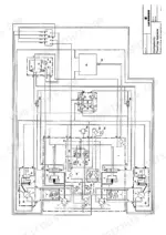
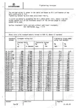
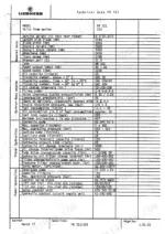
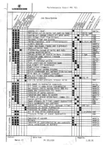
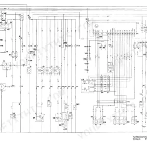
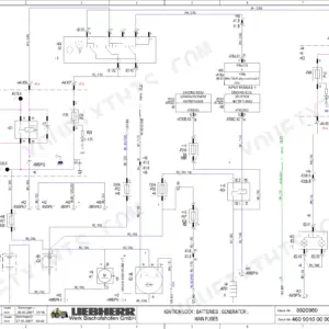
Straight from Liebherr and laid out in the factory's own eleven chapters, this 342-page Liebherr PR 721, PR 731, PR 741 service manual PDF covers all three crawler dozers in the range. Drive hydraulics alone fill roughly a quarter of the book, with operating pressures, test instructions and hydraulic schematics tracing the travel circuit, while the electrical chapter carries wiring diagrams for following a dead circuit back to its source. Your undercarriage work is covered too: running gear wear limits, track adjuster and lower roller service, and travel drive removal through reassembly. Measure track pins and bores against the factory figures: 3 mm is the wear limit, and at 5 mm the parts get renewed. Every hour a dozer sits idle costs you. Exploded views show how each assembly goes together, so you order the right component the first time, and bookmarks plus searchable text jump straight to any chapter.
What's Inside This Liebherr PR 721, PR 731, PR 741 Manual
| System | Pages | Key Topics |
|---|---|---|
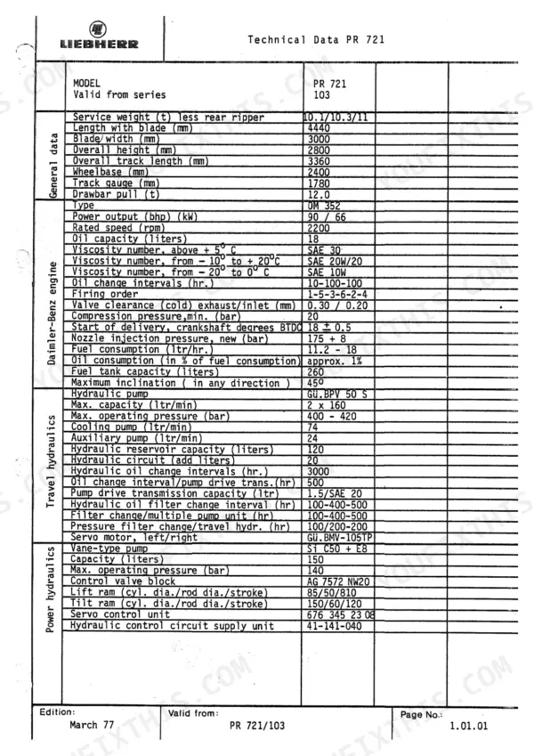
| Technical Data | 7-16 | Technical Data PR 721, Technical Data PR 731, Technical Data PR 741 |
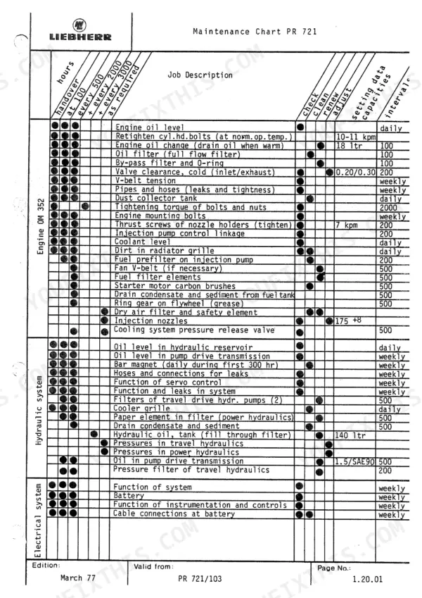
| Engine | 17-24 | Maintenance Chart PR 721, Maintenance Chart PR 731, Maintenance Chart PR 741 |
| Drive Hydraulic | 25-114 | Operating Pressures, Test Instructions, Travel Hydraulics Components |
| Working Hydraulic | 115-146 | Table of Pressures, Test Instructions, Hydraulic Components |
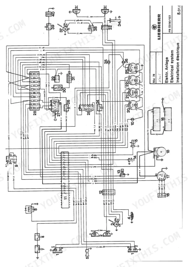
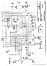
| Electrical System | 147-194 | Electrical System Components, Electrical System Diagrams |
| Track Drive | 195-220 | Travel Drive Removal, Travel Drive Disassembly, Travel Drive Assembly |
| Running Gear | 221-284 | Wear Limits, Track Adjuster, Lower Roller |
| Track Frames | 285-306 | Lower Roller Frame Removal, Lower Roller Frame Installation, Swing Beam |
| Attachment | 307-324 | Pusher Frame Removal, Pusher Frame Adjustment, Pusher Frame Installation |
| Tools | 325-332 | Ring Nut Wrench, Filling Apparatus, Adapter Flange |
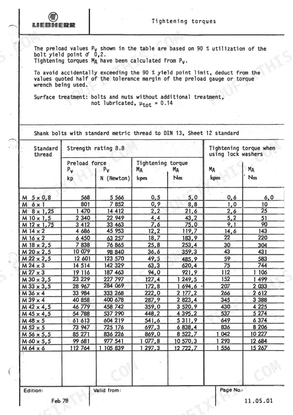
| General Information | 333-342 | Tightening Torques, Ermeto Unions |
Quick Reference Specifications
| Specification | Value | Page |
|---|---|---|
| All Models | ||
| Track tension | 2 cm | p. 22 |
| Track pin and bore wear limit | 3 mm | p. 225 |
| Track pin and bore renewal limit | 5 mm | p. 225 |
| Track tension sag | 2 cm | p. 235 |
| PR 721 Drive sprocket tooth flank wear | 6-8 mm | p. 229 |
| PR 731 Drive sprocket tooth flank wear | 6-8 mm | p. 229 |
| PR 721 M/103, 731/102, 741/106 | ||
| Reservoir of hydraulic circuit supply unit operating pressure | 30 bar ± 2 bar | p. 133 |
| PR 721 M/155 | ||
| Max. operating pressure (supply pressure) | 18 bar | p. 133 |
| PR 741 | ||
| Tightening torque for M 24 x 3 shank bolts (Strength rating 10.9) | 1 046 Nm | p. 334 |
| PR 721 | ||
| Engine Oil Capacity | 18 liters | p. 9 |
| Fuel Tank Capacity | 260 liters | p. 9 |
| Max. travel speed | 10.5 km/h | p. 10 |
Liebherr PR 721, PR 731, PR 741 Common Problems This Manual Covers
Liebherr PR 721, 731, 741 crawler dozer will not hold straight ahead travel below 10 km/h
Check top speed and straight ahead travel at minimum pitch first, and note which track lags. Then adjust straight ahead travel using the Drive Hydraulic test instructions starting on page 25. If the machine still drifts, check and set the pressure differential at the load limiting valve, because that setting also governs straight ahead travel.
Manual Section: Drive Hydraulic p. 25Travel hydraulics load limiting valve out of adjustment with excessive engine droop under travel load
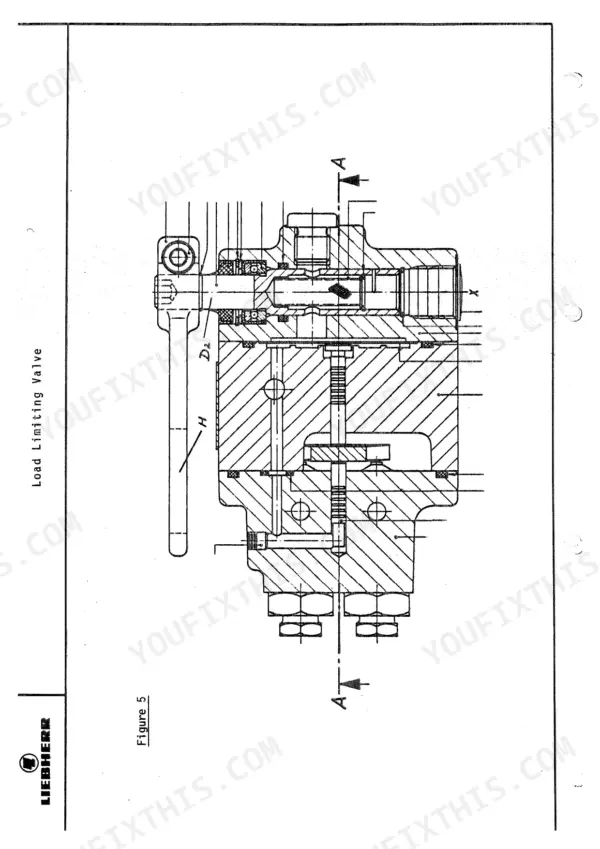
Check the pressure differential at the load limiting valve with gauges installed per the test instructions, then measure engine droop. Set the differential following the load limiting valve check and setting procedure on page 35. Recheck straight ahead travel afterward, because the same setting affects tracking.
Manual Section: Load limiting valve adjustment p. 35Drive hydraulic supply pressure or flushing circuit pressure off spec at the pressure limiting valves
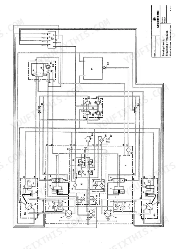
Test the high pressure valves, supply pressure and flushing circuit following the Pressure limiting valve testing procedure, and trace each line on the drive hydraulic schematic. Check the cold start valve, servo motors and auxiliary pump next. If supply pressure stays low, inspect the variable pitch pump gear pump and feed pressure valve.
Manual Section: Pressure limiting valve testingWorking hydraulic circuit supply unit operating pressure reads high or low on the gauge
Measure the supply unit operating pressure following the Working Hydraulic test instructions and compare it with the value listed on page 133. On PR 721 M/103, 731/102 and 741/106 machines it should read 30 bar ± 2 bar. Confirm the machine version before judging the reading, because other versions list different values.
Manual Section: Working Hydraulic p. 133Track pins, bushings and drive sprocket tooth flanks showing heavy wear on the running gear
Measure track pin and bore wear against the 3 mm wear limit on page 225; at 5 mm the parts need renewal. Check the bushing outer running face against 3 to 3.5 mm. Then measure drive sprocket tooth flank wear against the 6 to 8 mm reconditioning limit on page 229 before ordering parts.
Manual Section: Track maintenance p. 225Track adjuster will not hold tension and track chain sag exceeds the specified setting
Measure track sag and compare it with the 2 cm setting on page 235, then adjust tension at the track adjuster. If the sag comes back after adjustment, remove the adjuster and inspect the spring assembly and hydraulic cylinder, following the Track adjuster maintenance procedure for disassembly and assembly.
Manual Section: Running Gear p. 235Frequently Asked Questions
How often are the hydraulic filters changed on the Liebherr PR 721?
The PR 721 maintenance chart on page 17 lists the filters of the travel drive hydraulic pumps (2) and the paper element in the power hydraulics filter for renewal every 500 hours. p. 17
What are the replacement specs for fuel filters and water separator elements on the Liebherr PR 721?
The fuel filter elements for the PR 721, PR 731, and PR 741 should be replaced every 500 operating hours. p. 17
What is the correct valve clearance for the PR 721 engine?
The valve clearance for the PR 721 engine (cold) is 0.30 mm for the exhaust and 0.20 mm for the inlet. p. 9
What is the engine oil capacity for the PR 731?
The engine oil capacity for the PR 731 is 22 liters. p. 19
What is the tightening torque for the cylinder head bolts on the PR 741?
The cylinder head bolts on the PR 741 should be retightened to 20 mkp at normal operating temperature. p. 21
What do I get after purchasing this Liebherr PR 721 manual?
Immediate download of the complete 342-page searchable Service Manual. Access it on any device, from a laptop at your desk to a phone in the field.
Is printing allowed for this Liebherr PR 721 Service Manual?
Yes. Many buyers print one chapter at a time for their own shop and keep the rest on a tablet.


Reviews
There are no reviews yet.