
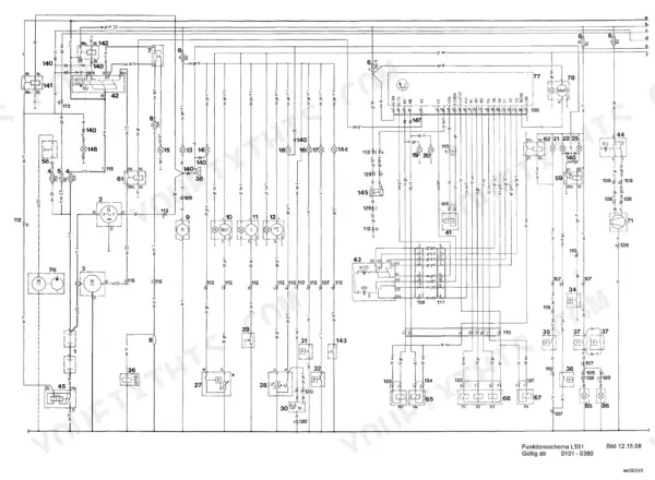
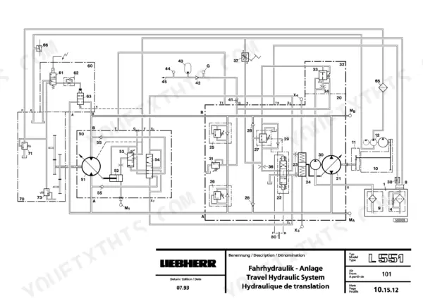
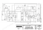
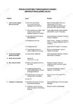
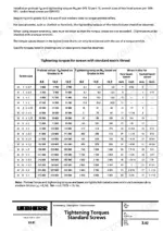
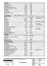
Travel and working hydraulics, the powershift transmission, steering, brakes and the electrical system are each worked through end to end in this Liebherr L551 service manual PDF, a 477-page book for the wheel loader under Liebherr ID 8145009. Hydraulic schematics trace oil from the control valve block past the primary and secondary relief valves to the lift and tilt cylinders, and wiring diagrams follow each circuit from battery and fuse box to the alternator, starter and glow plugs. Travel hydraulics fill a large share of the book, from travel pump and inching valve to the crossover relief valves, and troubleshooting charts sit inside the engine and powershift transmission sections. Fill the hydraulic tank with 200 L and swap the return filter every 500 hours. Alone with a stalled loader, nobody is there to ask. Your copy is bookmarked by section, text-searchable, and rides along on whatever device you carry to the machine.
What's Inside This Liebherr L551 Manual
| System | Pages | Key Topics |
|---|---|---|
| General Information | 1-6 | Introduction, Explanation of Numbering System |
| Accident Prevention Guidelines | 7-18 | General Safety Information |
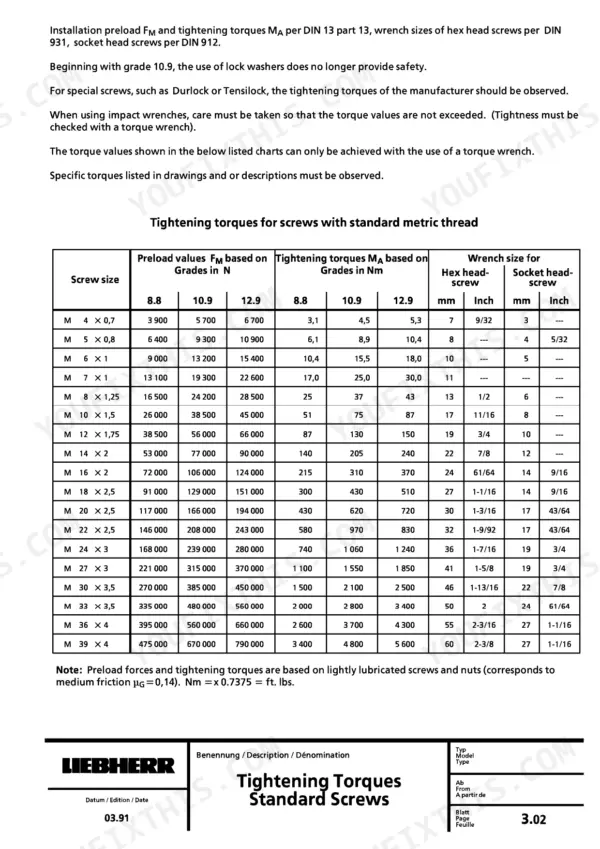
| General Technical Data | 19-33 | Conversion Chart, Tightening Torques, Material Classification |
| Special Tools | 34-94 | General Special Tools, Special Tools for Engine, Special Tools for Electric System, Special Tools for ZF Axles |
| Repair Welding | 95-100 | Preparation of a Crack, Preparation of a Weld, Storing Electrodes, Welding Technique, Reinforcement of the Welding Seam, Reinforcement Plates |
| Lubricants | 101-109 | Lubrication Chart |
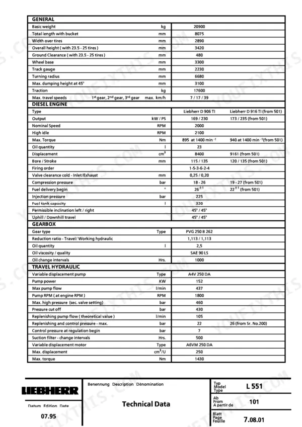
| Technical Data and Inspection Schedules | 110-143 | Adjustment Checklist, Maintenance and Inspection Work |
| Diesel Engine | 144-164 | Technical Features |
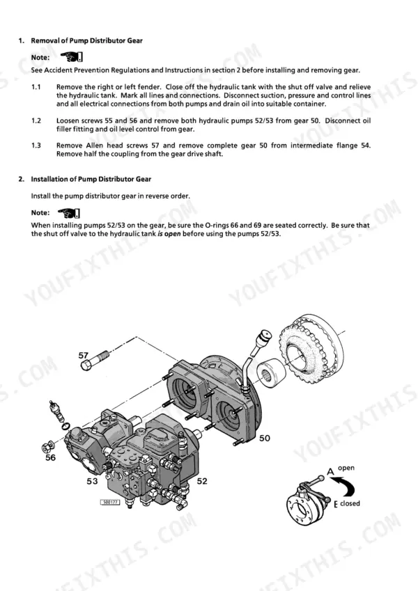
| Pump Distributor Gear | 165-172 | Intermediate Flange, Gear Drive Shaft, Coupling, Gear Housing |
| Travel Hydraulic System | 173-234 | Travel Pump, Variable Displacement Motor, Regulator Valve, Replenishing Pressure Relief Valve, Crossover Relief Valves, Inching Valve |
| Working Hydraulic System | 235-298 | Control Valve Block, Primary Pressure Relief Valve, Secondary Pressure Relief Valves, Lift Cylinder, Tilt Cylinder, Flow Divider Valve |
| Electrical System | 299-334 | Battery, Fuse Box, Alternator, Starter, Glow Plug, Indicator Lights |
| Heating and Ventilation System | 335-340 | Heat Exchanger, Fan, Air Ducts, Thermostat Valve, Blower, Fresh Air Vent |
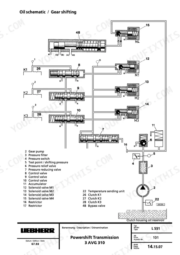
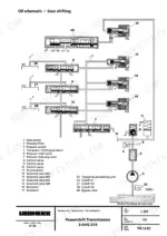
| Powershift Transmission | 341-380 | Planetary Gears, Hydraulic Clutches, Gear Pump, Pressure Filter, Shifting Unit, Bypass Valve |
| Axles | 381-387 | Differential, Wheel Hub, Disk Brake, Planetary Drive, Oscillating Axle, Bearing |
| Steering System | 388-427 | Main Pump, Emergency Steering Pump, Valve Block, Servostat, Steering Cylinder, Flow Divider Valve |
| Brake System | 428-453 | Gear Pump, Cut Off Valve, Service Brake Valve, Parking Brake Valve, Accumulator, Disk Brake |
| Main Frame and Cab | 454-470 | ROPS, FOPS, Rubber Bushings, Articulation, Oscillating Axle, Instrument Panel |
| Lift Arms | 471-477 | Shovel Arm, Lift Cylinder, Tilt Cylinder, Bucket Return Device, Bucket Stops, Hoist Limit Switch |
Quick Reference Specifications
| Specification | Value | Page |
|---|---|---|
| Tightening torque for GE 6-LM fitting | 20 Nm | p. 26 |
| Tightening torque for GE 6-LR fitting | 20 Nm | p. 26 |
| Hydraulic oil filter change interval | 500 hrs | p. 107 |
| Hydraulic oil tank capacity | 200.0 L | p. 109 |
| Return filter change interval | 500 Hrs. | p. 114 |
| Pressure filter change interval (Powershift Transmission) | 500 Hrs. | p. 114 |
| Fuel Filter Pre-Filter | 50 - 60 µm | p. 157 |
| Fuel Filter Fine Filter | 7 µm | p. 157 |
| Replenishing Pressure (bis S/N:199) | 22 ± 2 bar | p. 174 |
| Replenishing Pressure (from S/N:200) | 26 ± 2 bar | p. 174 |
| Engine Oil Quantity | 23 L | p. 113 |
| Fuel Tank Capacity | 320 L | p. 113 |
Liebherr L551 Common Problems This Manual Covers
Liebherr L551 travel hydraulics: regulation begin, crossover relief valve or pressure cutoff readings out of spec
Check replenishing pressure first: 22 ± 2 bar up to S/N 199, 26 ± 2 bar from S/N 200 (page 174). Test regulation begin on page 188 for 40 to 50 bar at MB with 6 to 8 bar at X3. Then verify the crossover relief valves build 460 ± 20 bar (page 189) and the pressure cutoff reaches 430 ± 5 bar (page 190).
Manual Section: Travel Hydraulic System Troubleshooting p. 188Working hydraulics give little output and jerky movements, attachment drifts under load, spools not returning
Check primary pressure relief valve 60 against 290+5 bar on page 236. Then check the secondary valves: 310+5 bar for tilt cylinder valves 64 and 65, and 340+5 bar for lift cylinder extend valve 67. Inspect the control valve block spools for sticking, and trace the circuit on the schematic.
Manual Section: Working Hydraulic System Troubleshooting p. 236Powershift transmission shift pressure low with oil level rising in the gear housing
Measure shift pressure at shift pressure valve 6 against 16 ± 2 bar on S/N 101-380 or 15 +4 bar from S/N 381, and servo pressure at pressure reducing valve 7 against 4 to 5 bar, as listed on page 346. If oil level keeps climbing in the gear housing, test for internal leakage following page 359. Replace the transmission pressure filter every 500 hours.
Manual Section: Powershift Transmission Troubleshooting p. 359Steering wheel hard to turn or blocked, machine steers opposite side, flow indicator lights up
Check the output of the main pump and the emergency steering pump first. Inspect the valve block, flow divider valve and servostat, then the steering cylinder, working through the steering section from page 388. If the flow indicator lights up, also check the working hydraulics for a failure.
Manual Section: Steering System Troubleshooting p. 388Service brake gives poor or no braking effect, or the brake will not open
Measure service brake pressure against the 65 bar maximum on page 114. Inspect the accumulator, cut off valve and gear pump, then the service brake valve. If the brake will not open, check the parking brake valve and the disk brake, working through the brake section from page 428.
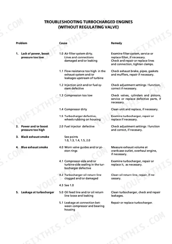
Manual Section: Brake System Troubleshooting p. 428Diesel engine lacks power with low boost pressure and black or blue exhaust smoke
Check boost pressure first, then inspect the turbocharger for leakage using the troubleshooting chart on page 155. Verify high idle reaches 2150 ± 50 RPM per page 186. Inspect the fuel pre-filter (50 to 60 µm) and fine filter (7 µm) listed on page 157 before chasing black or blue smoke any further.
Manual Section: Engine Troubleshooting p. 155Frequently Asked Questions
What are the replacement specs for the hydraulic return and transmission filters on a Liebherr L551?
The return filter element for the hydraulic system should be replaced every 500 operating hours. The pressure filter insert for the powershift transmission should also be replaced every 500 operating hours. p. 115
What are the replacement specifications for the engine fuel filters and water separator elements on the Liebherr L551?
The fuel filter should be checked and cleaned if necessary, and the fuel filter cartridge (1st and 2nd stage) should be replaced. The water separator at the fuel filter should be checked and emptied if necessary. p. 115
What is the tightening torque for the main bearing cap on the Liebherr D 906 TI / D 916 TI engine?
Page 157 gives the main bearing cap procedure for the D 906 TI and D 916 TI: lubricate the thread and head contact surface, pre-torque all screw connections to 30 Nm, then tighten in three angle stages of 30° each, 90° in total. p. 157
What is the correct valve clearance for the Liebherr D 906 TI / D 916 TI engine?
The valve clearance for the engine when cold is 0.20 mm for the inlet valves and 0.25 mm for the exhaust valves. p. 156
What is the engine oil change capacity, including the filter, on the Liebherr L551?
The engine oil capacity for an oil change including the filter is 26 liters (6.9 gallons). p. 156
What format is this Liebherr L551 manual in?
You download the Service Manual yourself: 477 pages, searchable PDF, available immediately. Keep a copy on every device you use.
Can I print specific sections of this Liebherr L551 Service Manual?
Yes. Print a single page or a chapter for your own shop use, on letter or A4.


Reviews
There are no reviews yet.