
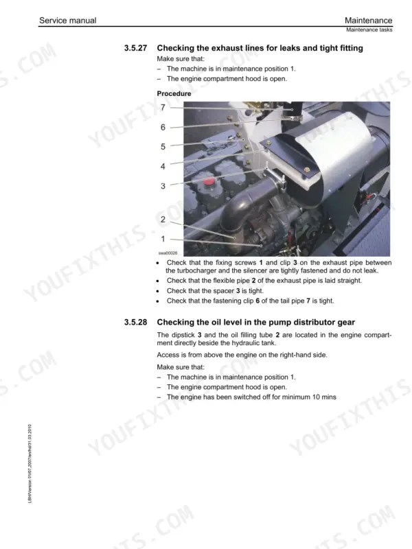
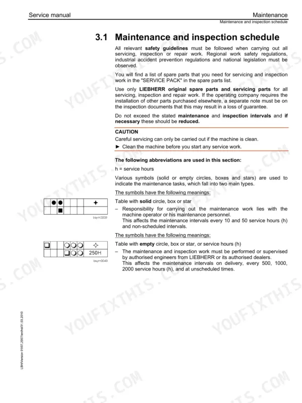
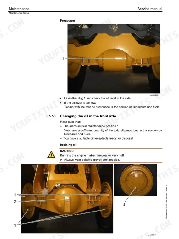
Travel hydraulics are the toughest system on the L586 2plus2 wheel loader, and this 703-page Liebherr L586 2plus2 service manual PDF works through its variable displacement pumps and motors before widening to transfer gear, axles, steering, brakes and the articulation bearing. The electrical chapter, the largest in the book at roughly a fifth of it, carries the wiring diagrams; hydraulic schematics lay out the working circuit from control block and pilot control unit to the lift and tilt cylinders and ride control. A closing chapter on service codes and diagnosis lets you match a stored fault to its cause before a fitting comes loose. Set the working pump flow regulator to 22 ± 2 bar, confirm power control starts regulating at 180 ± 10 bar, and torque wheel nuts to 450 Nm. Guess at a pump setting and you pay twice: new parts, second teardown. Bookmarked and text-searchable, it is bought once and stays yours for as long as the loader works your yard.
What's Inside This Liebherr L586 2plus2 Manual
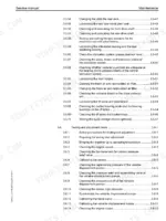
| System | Pages | Key Topics |
|---|---|---|
| General Information | 1-22 | Safety Regulations, Special Tools for Maintenance |
| Product Description | 23-44 | Technical Data |
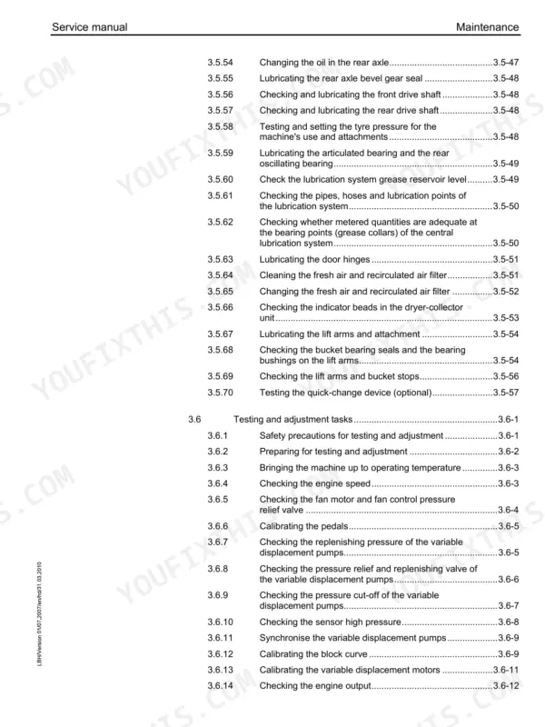
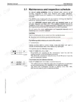
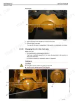
| Maintenance | 45-143 | Maintenance and Inspection Schedule, Testing and Adjustment Plan, Maintenance Tasks |
| Diesel Engine and Pump Distributor Gear | 144-167 | Diesel Engine, Fuel System, Air Filter System, Coupling, Pump Distributor Gear |
| Cooling System | 168-183 | Gear Pump, Gear Motor, Temperature Sensor |
| Travel Hydraulics | 184-235 | Variable Displacement Pumps, Variable Displacement Motors |
| Working Hydraulics | 236-301 | Control Block, Pilot Control Unit, Ride Control, Lift and Tilt Cylinders, Hydraulic Tank |
| Steering System | 302-335 | Steering Pump, Servostat, Steering Cylinder, Emergency Steering |
| Brake System | 336-365 | Service Brake, Parking Brake, Overspeed Protection |
| Electrical System | 366-513 | Electrical Components, Battery Installation |
| Transfer Gear | 514-535 | Mechanical Transmission, Electronic Control Unit, Hydraulic Control |
| Axles and Cardan Shaft | 536-555 | Front Axle, Front Axle Flushing Circuit, Rear Axle, Drive Shafts |
| Machine Frame and Ballast Weight | 556-567 | Machine Frame, Articulation Bearing, Oscillating Bearing, Articulation Lock, Ballast Weight |
| Central Lubrication System | 568-581 | Automatic Central Lubrication System |
| Coverings and Access | 582-591 | Covering, Cab Access |
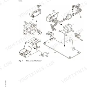
| Cab, Heating and Air-Conditioning | 592-627 | Display Unit, Heating, Ventilation, Air Conditioning, Air Conditioning System |
| Lift Arms and Quick-Change Device | 628-641 | Lift Arms, Pin Bearing, Quick Change Device |
| Equipment and Accessories | 642-645 | Bucket |
| Service Codes and Diagnosis | 646-702 | Malfunctions |
| Options | 703 |
Quick Reference Specifications
| Specification | Value | Page |
|---|---|---|
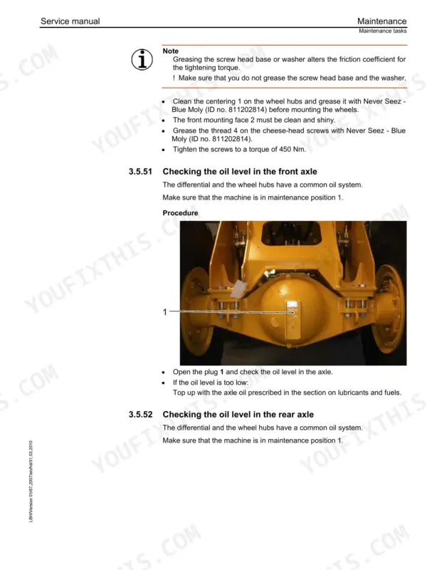
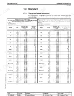
| Wheel lug tightening torque | 450 Nm | p. 37 |
| Wheel nut tightening torque | 450 Nm | p. 107 |
| Filter unit filtration grade | 10 µm | p. 32 |
| Bleeder filter filtration grade | 10 µm | p. 33 |
| Working hydraulics pump flow regulator (delta p) | 22 ± 2 bar | p. 30 |
| Working hydraulics pump power controller start of regulation | 180 ± 10 bar | p. 30 |
| Variable displacement motor 1 torque (Δp 400 bar) | 878 Nm | p. 29 |
| Variable displacement motor 2 torque (Δp 400 bar) | 908 Nm | p. 29 |
| Gear shifting solenoid valves resistance | 93 ± 6 Ohm | p. 37 |
| Replenishing pressure pump 1 | 34 ± 1 bar | p. 57 |
| Replenishing pressure pump 2 | 34 ± 1 bar | p. 57 |
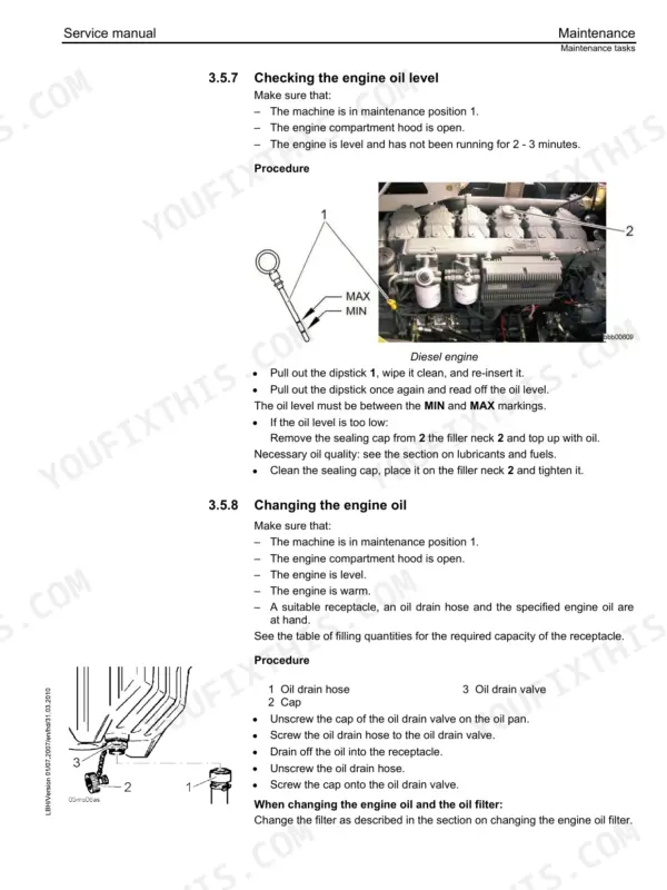
| Engine Oil Capacity | 43.0 L | p. 60 |
Liebherr L586 2plus2 Common Problems This Manual Covers
Liebherr L586 2plus2 transfer gear will not shift, low coupling or servo pressure during testing
Measure transfer gear switching pressure against 20 ± 3 bar from the test values on page 59, then work through the coupling, accumulator, lubricating and servo pressure checks in the 2plus2 transfer gear fault location. Test the gear shifting solenoid valves for 93 ± 6 Ohm before condemning the hydraulic control on page 514.
Manual Section: Transfer Gear p. 514Travel hydraulics weak under load, low replenishing pressure on pump 1 or pump 2
Check replenishing pressure on pump 1 and pump 2 against 34 ± 1 bar using the travel hydraulics test values on page 57. If replenishing pressure holds, verify the forward and reverse high pressure relief valves at 435 ± 10 bar and the high pressure cut off at 400 ± 5 bar before pulling the variable displacement pumps or motors.
Manual Section: Travel Hydraulics p. 184Lift arms slow or weak raising a loaded bucket, working hydraulic pressure low at the control block
Test the primary pressure relief valve against 380 ± 5 bar and the LS pressure cut off at boom lifting against 330 ± 5 bar, listed on page 58. Then check the working hydraulic pump power regulator at 180 ± 10 bar and the flow regulator pressure difference at 23 ± 2 bar in float position at 1500 rpm.
Manual Section: Working Hydraulics p. 236Control valve block leaking oil, lift or tilt cylinders drifting with the load held
Clean the control block dry, then run the oil leak monitoring check from the working hydraulics troubleshooting. Measure cylinder travel on the lift and tilt cylinders with the bucket raised. Check the lift, tilt in and tilt out secondary pressure relief valves against 400 ± 5 bar from page 58.
Manual Section: Working Hydraulics p. 236Emergency steering fails its function test, steering pressure switch not signaling at the valve block
Run the emergency steering function test and the pressure switch tests from the steering system troubleshooting before touching the Servostat. Verify steering pump pressure cut off at 210 ± 5 bar, then check valve block operation following the steering system section on page 302.
Manual Section: Steering System p. 302Brake accumulators slow to charge, low brake pressure warning while working the loader
Check accumulator charge pressure at the compact brake valve: cut in should read 180 ± 5 bar and cut out 210 ± 5 bar per page 59. Test the brake system pressure switch switching point at 120 ± 5 bar, then verify brake pressure in the axles reaches 70 ± 5 bar.
Manual Section: Brake System p. 336Frequently Asked Questions
What are the hydraulic pressure settings for the high pressure relief valves on the Liebherr L586 2plus2 travel hydraulics?
For the travel hydraulics, the high pressure relief valve setting for forward travel is 435 bar, and for reverse travel, it is also 435 bar. These values are subject to a tolerance of ±10 bar. p. 57
What is the correct tightening torque for the wheel nuts on the L586 2plus2?
The wheel nuts on all four wheels must be tightened to a torque of 450 Nm using a 17 mm hex socket. p. 107
What is the capacity of the hydraulic tank for the L586 2plus2?
The hydraulic tank has a capacity of 180 liters. p. 60
What is the correct valve play for the engine inlet and outlet valves?
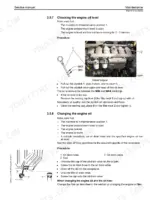
The valve play for the inlet valve (cold) is 0.30 mm, and for the outlet valve (cold) it is 0.40 mm. p. 74
What is the procedure for depressurising the ride control system?
To depressurise the ride control system, put the machine in maintenance position 2, turn off the engine, and connect a 40 bar manometer to test connection M4 on the front axle and test connection MX. The pressure will relieve through this line to the tank in approximately 10 minutes. p. 137
How will I receive this Liebherr L586 2plus2 Service Manual?
A 703-page Service Manual in searchable PDF format, available the moment you complete checkout. View on computer, tablet, or phone, with no shipping wait.
Is this Liebherr L586 2plus2 manual print-friendly?
Yes. Print the pages or sections you need for your own shop use. Any standard printer works.


Reviews
There are no reviews yet.