
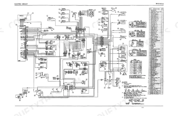
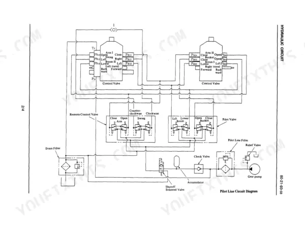
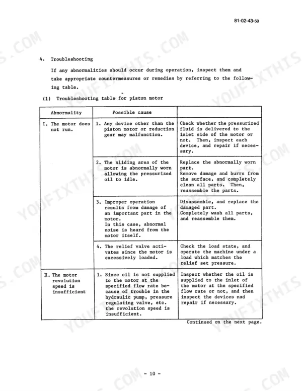
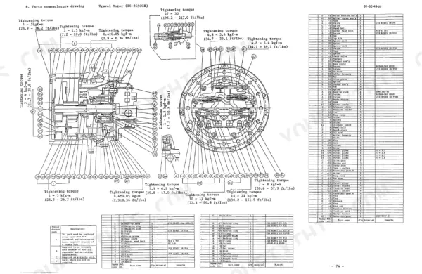
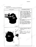
Book No. F00055 0193 identifies this Link-Belt LS-2650, LS-2650C shop manual PDF as the factory original: 372 pages written for the older LS-series hydraulic excavators. Hydraulic circuit diagrams trace oil from the pump and control valve to the boom, arm and bucket cylinders, swing motor and travel priority valve, while the electric circuit pages map the monitor display, throttle motor, solenoid valves and sensors. The travel motor and reduction gear section fills about a fifth of the book, and the undercarriage chapters take your take-up roller, carrier roller, track roller and recoil spring apart and back together. Check suction strainer D at 50 mm (1.97 in) before refitting, then torque the drain plug to 4 kgf-m (28.9 ft lbs). Some days it is just you, the machine and nobody to call. The bookmarked, text-searchable PDF and its sectional drawings let you identify the exact seal or bearing, so the part number you order is right the first time.
What's Inside This Link-Belt LS-2650 C Series II Manual
| System | Pages | Key Topics |
|---|---|---|
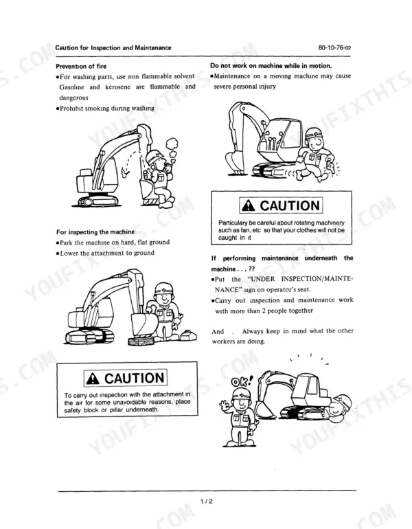
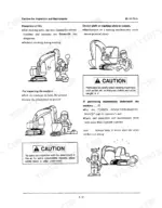
| Caution for Inspection and Maintenance | 5-6 | Prevention of Fire, Machine Inspection, Rotating Machinery, Maintenance Underneath Machine, Inspection with Attachment in Air, Hot Machine Components, Tool Usage |
| Basic Rules | 7-12 | General Rules for Disassembling, General Rules for Reassembling, Handling of the Interchangeable Parts |
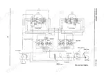
| Hydraulic Circuit | 13-16 | Travel Motor Relief Pressure, Arm Cylinder, Boom Cylinder, Bucket Cylinder, Swing Motor, Travel Priority Valve, Hydraulic Pump, Control Valve |
| Electric Circuit | 17-18 | Monitor Display, Solenoid Valve, Throttle Motor, Horn, Working Lamp, Fuel Sensor, Water Temperature Sensor, Battery |
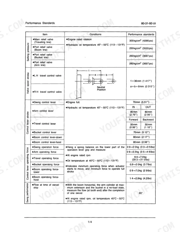
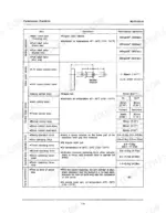
| Performance Standards | 19-28 | Main Relief Valve, Port Relief Valve, Valve Spool Stroke, Control Lever Operating Force, Swing Performance, Travel Speed, Travel Bend, Cylinder Speed, Pump Oil Filling, Air Bleeding, Engine Speed, Oil Leakage Check, Solenoid Proportional Pressure Control Valve, Travel Motor Oil Filling, Swing Motor Oil Filling, Grease Lubrication, Suction Strainer Dimensions, O-Ring Specifications |
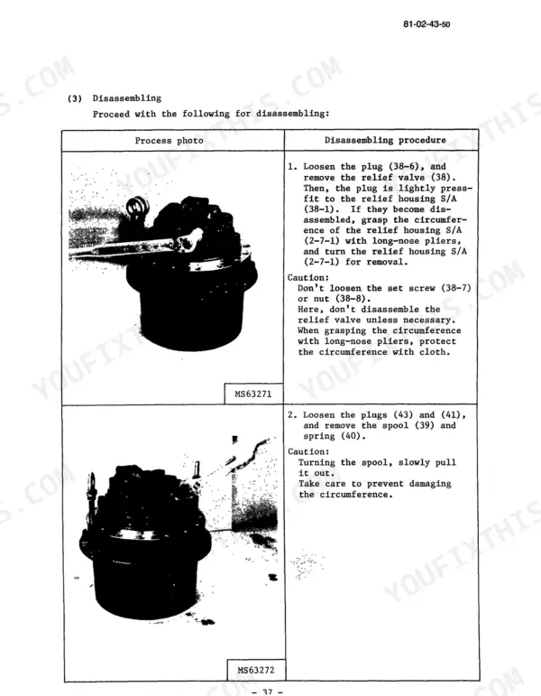
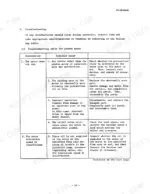
| Traction Motor and Reduction Gear | 29-108 | Cautionary Points for Handling, Operating Procedure and Cautionary Points, Periodic Inspection and Replacement, Troubleshooting, Maintenance Procedure |
| Traction Drive Assembly | 109-110 | Bolt Tightening Torque, Traction Drive Configuration |
| Take-Up Roller | 111-146 | Disassembly Procedure, Reassembly Procedure, Carrier Roller, Track Roller |
| Grease Cylinder, Recoil Spring | 147-148 | Yoke, Spring Pin, Castle Nut, Recoil Spring, Rod, Grease Cylinder Dust Seal, Grease Nipple, Check Valve |
| Recoil Spring and Roller | 149-162 | Structural Diagram, Tools and Jigs, Disassembly Procedure, Reassembly Procedure |
| Shoe and Drive Sprocket | 163-168 | Structural Diagram, Tools, Disassembly and Reassembly of Shoes, Track Link Replacement, Maintenance Standards, Drive Sprocket |
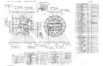
| Swing Motor and Reduction Gear | 169 | Swing Reducer Sectional Drawing, Parts List, Swing Motor Sectional Drawing |
| Swing Motor Assembly | 170-224 | Cautions Regarding Handling, Parts List, Disassembly, Reassembly, Maintenance Standards, Troubleshooting |
| Engine Mounting | 225-226 | Engine Mounting Bolt Tightening Torque |
| Hydraulic Pump | 227-274 | Disassembly and Reassembly, Pump Installation, Coupling Sectional View, Periodic Checking and Change Periods |
| Rotating Joint | 275-280 | Structural Diagram, Tools, Reassembly Procedure |
| Pilot Valve | 281-304 | Maintenance, Troubleshooting |
| Control Valve | 305-328 | Cautions in Handling, Disassembly and Reassembly Procedure, Troubleshooting |
| Hydraulic Cylinder | 329-346 | Trouble, Maintenance Standard, Disassembly Procedure, Reassembly Procedure |
| Service Monitoring System | 347-362 | Outline, Performance, Function and Construction Description, Monitor Display Block Diagram, Specifications, Disassembly and Reassembly, Procedure for Installing the Monitor |
| Weight of Components | 363-364 | Travel Motor, Drive Sprocket, Carrier Roller, Track Roller, Hydraulic Pump, Control Valve |
| Maintenance Standards (Back-Hoe Attachment) | 365-368 | Frame, Boom, Pin, Bushing, Arm, Bucket |
| Conversion Table | 369-372 | Weight, Length, Capacity, Pressure, Torque, Temperature |
Quick Reference Specifications
| Specification | Value | Page |
|---|---|---|
| Drain plug tightening torque | 4 kgf-m (28.9 ft.lbs) | p. 223 |
| Plug P-51 Tightening Torque | 4 kgf·m (28.9 ft lbs) | p. 223 |
| Suction strainer D (LS-2600/2650) | 50mm (1.97") | p. 230 |
| Suction strainer E (LS-2600/2650) | 10mm (0.39") | p. 230 |
| Bolt M16 x 55 Tightening Torque | 27.4-32 kgf·m (198.2-231.5 ft lbs) | p. 223 |
| Nut P-32 Tightening Torque | 10 kgf·m (72.3 ft lbs) | p. 273 |
| Maximum displacement | 2 x 63 cc/rev (2.08 oz/rev) | p. 227 |
| Maximum operating pressure | 300 kgf/cm² (4266 psi) | p. 227 |
| Pilot pump maximum pressure | 40 kgf/cm² (569 psi) | p. 227 |
| Cushion cylinder local wear replacement standard | 0.20mm (0.008") | p. 335 |
| Piston local wear replacement standard | 0.20mm (0.008") | p. 335 |
| Main relief valve (Traveling line) setting pressure | 300 kg/cm² (4266 psi) | p. 19 |
Link-Belt LS-2650 C Series II Common Problems This Manual Covers
Link-Belt LS-2650 travel motor does not run, has insufficient revolution speed, or revolution speed varies
Measure travel motor drain pressure first; page 33 calls for 2 kgf/cm² (28.4 psi) or less in ordinary state and 5 kgf/cm² (71.1 psi) instantaneous maximum. Then verify the traveling line main relief valve setting against 300 kg/cm² (4266 psi) on page 19 before working through the piston motor checks.
Manual Section: Piston Motor TroubleshootingHydraulic pump not discharging oil, showing low discharge pressure, or making abnormal noise
Check hydraulic oil level and look for filter clogging or piping restriction before condemning the pump. Then test pump pressure against the 300 kgf/cm² (4266 psi) maximum operating pressure at 2200 rpm input speed listed on page 227. Inspect the suction strainer and its oil stopper following page 27.
Manual Section: Hydraulic Pump p. 227Swing motor does not turn, shows large slip, insufficient torque, or abnormal heating
Check reduction gear oil at the level gauge first; page 25 specifies 2.2 to 2.3 liter (0.581 to 0.607 gal) and 500 cc of bearing grease. Inspect the motor for oil leaks and abnormal noise, then torque the drain plug to 4 kgf-m (28.9 ft.lbs) per page 223 on reassembly.
Manual Section: Swing Motor TroubleshootingControl valve spool sticking, negative load not being held, or negative load drops
Verify port relief settings on page 19 first: boom line 250 kg/cm² (3555 psi), arm and bucket lines 260 kg/cm² (3697 psi). Then remove and inspect the spools for sticking, following the control valve disassembly and reassembly procedure starting on page 305. Check for a cracked valve body while it is apart.
Manual Section: Control Valve p. 305Boom, arm or bucket cylinder showing local wear on the piston or cushion at teardown
Measure local wear on the piston and cushion after disassembly per the hydraulic cylinder procedure starting on page 329. Replace when wear reaches the 0.20mm (0.008") standard listed on page 335. Inspect pins and bushings against the back-hoe attachment maintenance standards on page 365 while the cylinder is out.
Manual Section: Hydraulic Cylinder p. 329Machine travel is not linear, with travel bend out of the performance standard
Test travel bend and travel speed against the performance standards on page 19 before tearing anything down. Then inspect the two-speed control function area, and check that both travel motors meet the 2 kgf/cm² (28.4 psi) ordinary drain pressure limit on page 33.
Manual Section: Two-Speed Control Function Area TroubleshootingFrequently Asked Questions
How do I troubleshoot hydraulic pressure loss on a Link-Belt LS-2650?
To troubleshoot hydraulic pressure loss, first check the main relief valve setting, which should be 300 kg/cm² (4266 psi) for the traveling line. If pressure is low, inspect the hydraulic pump, which has a maximum operating pressure of 300 kg/cm² (4266 psi). Refer to the troubleshooting tables on pages 40-42 for specific piston motor issues and pages 271-272 for pump-related pressure problems. p. 19
What are the replacement specifications for the main hydraulic pump on the Link-Belt LS-2650 C Series II?
The main hydraulic pump (Model PSV2-63T) has a maximum displacement of 2 x 63 cc/rev (2.08 oz/rev) and a maximum operating pressure of 300 kgf/cm² (4266 psi). The pilot pump has a displacement of 9.8 cc/rev (0.323 oz/rev) and a maximum pressure of 40 kgf/cm² (569 psi). p. 227
What is the standard oil capacity for the travel motor reduction gear case on the Link-Belt LS-2650 C Series II?
The standard oil capacity for the travel motor reduction gear case is 2500 cc (82.5 oz). When refilling, remove the plug of the oil fill/check port and fill until the oil overflows from the check port. p. 34
What is the tightening torque for the swing motor mounting bolts on a Link-Belt LS-2650 C Series II excavator?
The swing motor mounting bolts (M16 x 55 and M16 x 80) should be tightened to a torque of 27.4 to 32 kgf-m (198.2 to 231.5 ft lbs). p. 223
What is the procedure for checking the hydraulic oil level in the swing motor reducer?
To check the oil level in the swing motor reducer, dismount the plug of the oil supply port. The oil level should be confirmed by the level gauge; stop filling when the gauge indicates oil at the specified level. The standard volume is 2.2 to 2.3 liters (0.581 to 0.607 gal). p. 25
What format is this Link-Belt LS-2650 manual in?
Delivery is instant: a 372-page searchable PDF is yours the second checkout clears. Laptop, tablet, or phone, all fine.
Can I print this Link-Belt LS-2650 manual?
Yes. Print a chapter or just the pages for the job at hand, for use in your own shop. Any home or office printer works.


Reviews
There are no reviews yet.