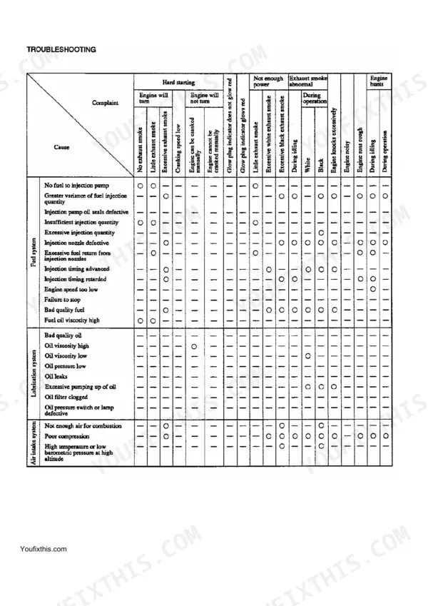
All 228 pages of this McCormick CT Series Service Manual cover the CT41 and CT47 tractors from S4Q engine internals through transmission, hydraulics, front axle, steering, and electrical systems. Inside: hydraulic schematics showing the complete 3-point linkage circuit with relief valve adjustment procedures, wiring diagrams for the starter motor and alternator, and a full troubleshooting section backed by system-level clearance data. You also get exploded views of the clutch housing, HST unit, and final drive, plus a factory torque table covering every critical fastener from head bolts to flywheel hardware. Set fuel injection timing at 20° B.T.D.C. and torque the cylinder head to 118±5 N·m; numbers like that don't come from a forum thread. No more chasing specs across a dozen PDF snippets stitched together by someone who's never seen your CT41 in the field. Download once, open on any device, and jump straight to any section with built-in bookmarks.
What's Inside This Manual
| System | Pages | Key Topics |
|---|
| Engine (S4Q) | 2-119 | Specifications, Cylinder Head and Valve Mechanism, Flywheel, Timing Gears, Camshaft, Balancer Shafts and Oil Pan, Pistons, Connecting Rods |
| Transmission | 120-162 | Clutch Housing, Shuttle and Creeper, Main Change and Counter Gear, HST Unit, Final Drive, Independent PTO |
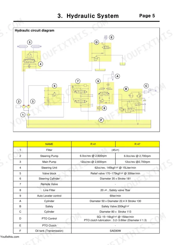
| Hydraulic System | 163-182 | Construction of Hydraulic System, Hydraulic Circuit, Hydraulic Housing, Control Valve, Adjustment of Linkage, Relief Valve |
| Front Axle | 183-198 | Knuckle Configuration, King Pin, Front Wheel Axle, Disassembling of Wheel Axle, Adjustment of Pinion Center Distance, Assembling of Differential Combination |
| Steering System | 199-211 | Description and Operation - Valve, Neutral Position, Disassembly and Assembly of Steering Valve, Disassembly of Rotor Shaft, Disassembly of Control Shaft |
| Starter Motor | 212-220 | Checking Before Disassembly, Checking of Magnetic Switch, Disassembly of Starter Motor, Inspecting of Each Component, Assembly of Starter Motor |
| Alternator | 221-226 | Checking Before Disassembly, Checking the Voltage of Alternator, Disassembly of Alternator, Overhaul and Inspection of Alternator, Assembly of Alternator |
| Fuel Solenoid | 227-228 | Fuel solenoid(R36), Outline, Operation, Assembly of Fuel Solenoid, Pre-Heater, Check of Glow Plug |
Quick Reference Specifications
| Specification | Value | Page |
|---|
| All Models |
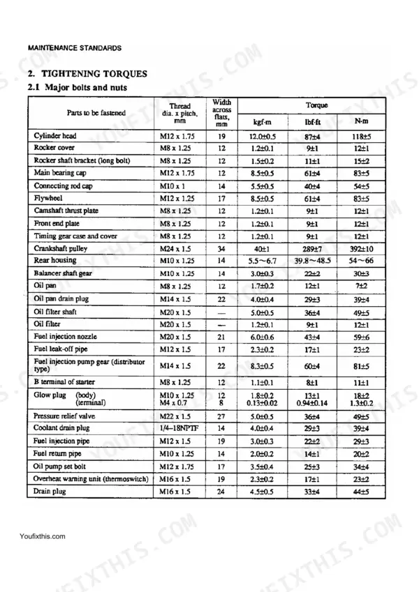
| Cylinder head bolt torque | 12.0±0.5 kgf·m (87±4 lbf·ft) [118±5 N·m] | p. 24 |
| Main bearing cap bolt torque | 8.5±0.5 kgf·m (61±4 lbf·ft) [83±5 N·m] | p. 114 |
| Fuel injection pump gear (distributor type) torque | 8.3±0.5 kgf·m (60±4 lbf·ft) [81±5 N·m] | p. 114 |
| Fuel injection timing | 20° B.T.D.C. | p. 108 |
| Fuel filter replacement interval | Every 250 service hours | p. 117 |
| Thermostat valve starts opening temperature | 76.5±1.5°C (170±2.7°F) | p. 74 |
| Thermostat valve lift at 8mm (0.3 in.) | 90°C (194°F) | p. 74 |
| Air cleaner (paper-element type) change interval | Every 250 service hours | p. 117 |
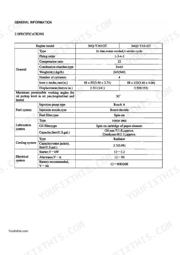
| Engine Compression Ratio | 22 | p. 5 |
| Engine Oil Pan Capacity | 7 L (1.8 U.S. gal) approx. | p. 5 |
| R41 |
| Main Pump displacement and RPM, R41 | 12cc/rev @ 2,600rpm | p. 167 |
| R47 |
| Main Pump displacement and RPM, R47 | 12cc/rev @ 2,700rpm | p. 167 |