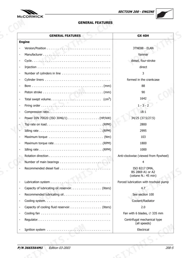
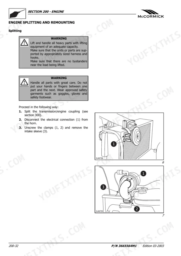
All 474 pages of this McCormick GX Service Manual (OEM #SM 8-30140 GB) are written for one tractor family: your GX 40H. Inside: wiring diagrams for every circuit from starting and recharging to operator safety and hydrostatic plant, plus hydraulic schematics covering the rear power lift and auxiliary control valves. You get a full troubleshooting section for engine and gearbox faults, standard driving torque tables for metric fasteners, and step-by-step overhaul procedures for the PTO hydraulic clutch, hydrostatic transmission housing, and bevel gear pair adjustment. Set injector pressure to 216–226 bar on the GX 40H, or 196–206 bar on the 45H/50H; torque the high-pressure fuel pipe sleeve nut to 29.4–34.3 Nm. Stop chasing electrical faults with a bad wiring diagram. Bookmarked and searchable, so you can jump to any system by keyword and get back under the hood.
What's Inside This McCormick GX 40H, GX 45H, GX 50H Manual
| System | Pages | Key Topics |
|---|---|---|
| General Information | 5-30 | Safety Notes, Danger Signs, Standard Driving Torque Values |
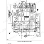
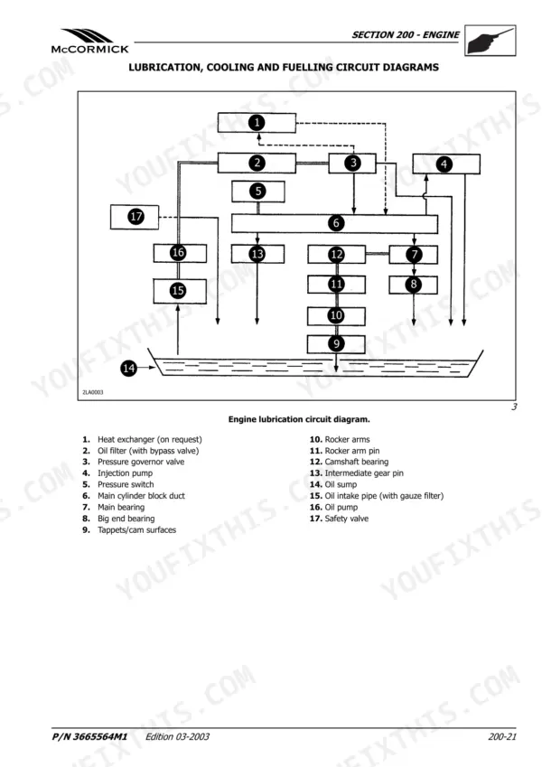
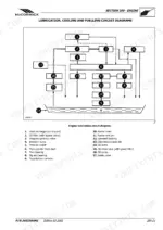
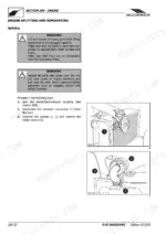
| Engine | 31-152 | General Features, Main Specifications, Lubrication, Cooling and Fuelling Circuit Diagrams, Engine Troubleshooting, Engine Splitting and Remounting, Compression Test |
| Engine/Transmission Coupling | 153-168 | Engine Coupling, Splitting-Remounting |
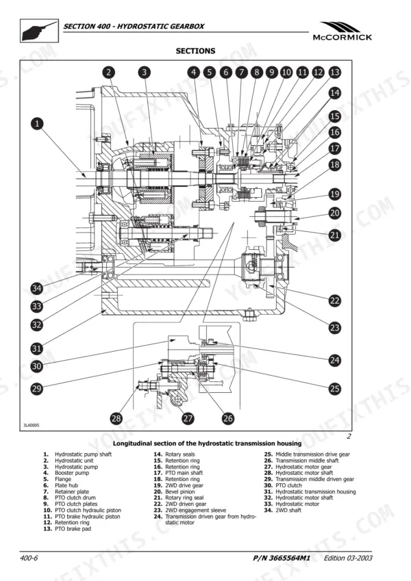
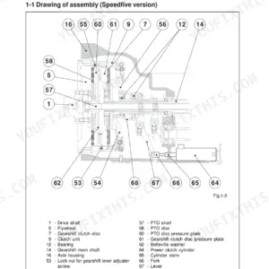
| Hydrostatic Gearbox | 169-216 | Sections, Troubleshooting for the Gearbox, Hydrostatic Transmission Housing - Splitting - Remounting, Hydrostatic Transmission Housing - Overhaul, PTO Hydraulic Clutch - Overhaul |
| Transmission | 217-278 | Driving Torque Values, Right or Left Side Final Drive Housing - Assembly Splitting Remounting, Driving Wheel Shaft - Overhaul, Bevel Gear Pair Adjustment |
| Power Take-Offs | 279-290 | Power Take-Off. Overhaul |
| Hydraulic Circuits | 291-336 | Sections and Perspective Views, Description of the Operating Mode of the Hydraulic Power Lift, Description of the Operating Mode of the Hydraulic Power Lift’s Valve System |
| Steering | 337-344 | Steering Cylinder, Hydrostatic Steering Pump, Control Valves, Pressure Filter, Rotary Pump, Differential Locking and Unlocking |
| Brakes | 345-356 | Main Brakes, Parking Brake, Oil-Cooled Discs, Pressure Plates, Control Rod, Flexible Steel Cables |
| Electrical System - Components | 371-382 | Maintenance |
| Electrical System – Ignition System | 383-392 | Starter Motor, Key-Switch, Electromagnet, Control Pinion, Battery, Ignition Relay |
| Electrical System – Recharging System | 393-402 | Tests and Troubleshooting |
| Electrical System - Battery | 403-414 | Maintenance and Battery Inspection |
| Electrical System – Electrical Circuits | 415-474 | Electrical System Components (Continued), Starting and Recharging Diagram (Diagram a), Operator Safety and Hydrostatic Plant Diagram (Diagram B/1) |
Quick Reference Specifications
| Specification | Value | Page |
|---|---|---|
| GX 40H | ||
| Injectors pressure setting, GX 40H | 216 ÷ 226 bar | p. 38 |
| GX 45H/GX 50H | ||
| Injectors pressure setting, GX 45H/GX 50H | 196 ÷ 206 bar | p. 38 |
| All Models | ||
| Auxiliary control valves maximum flow rate | 28 ÷ 36 l/min | p. 335 |
| Auxiliary control valves calibration pressure | 185 ÷ 190 bar | p. 333 |
| Thermostatic valve opening temperature | 69.5 ÷ 72.5 °C | p. 46 |
| Thermostatic valve lift height | ≥ 8.0 mm (≥ 85 °C) | p. 46 |
| Steering system filter filtering degree | 40 µm | p. 339 |
| Hydrostatic transmission external auxiliary cartridge filter | 10 micron | p. 178 |
| Engine oil cleaning type (on pump intake) | gauze filter | p. 39 |
| Engine oil cleaning type (on engine delivery) | cartridge filter | p. 39 |
| Steering circuit control valve unit adjustment pressure | 18 to 20 bar | p. 343 |
| Auxiliary control valves pressure setting | 185 ÷ 190 bar (188 ÷ 193 kg/cm²) | p. 329 |
McCormick GX 40H, GX 45H, GX 50H Common Problems This Manual Covers
McCormick GX 40H injection pump hard start or no-start condition, engine cranks but won't fire
Check the engine troubleshooting chart starting. Verify fuel supply and bleed the high-pressure lines. If the engine still won't fire, test injector opening pressure; spec is 216 ÷ 226 bar (page 38). Torque the high-pressure fuel pipe sleeve nuts to 29.4 ÷ 34.3 Nm on reassembly.
Manual Section: Engine TroubleshootingHydraulic lift drops under load or fails mid-operation, three-point hitch won't hold position
Inspect the hydraulic circuit for external leaks first. Test the over-pressure valve setting; it should read 185 ÷ 190 bar (page 293). If lift capacity falls short of the 1200 kg rated load, check that auxiliary control valve pressure holds at 185 ÷ 190 bar (page 329) and replace the cartridge filter if it's past interval.
Manual Section: Valve System of the Hydraulic Power Lift – Hydraulic Tests p. 293Engine temperature gauge climbs into red during normal field operation with no visible coolant leaks
Check fan belt tension first; it should deflect 10 ÷ 15 mm under moderate thumb pressure (page 87). Drain and flush the cooling system if you suspect sediment buildup. Test the thermostat by bench-boiling it; opening should begin at 69.5 ÷ 72.5 °C and reach full lift of at least 8.0 mm at 85 °C (page 46).
Manual Section: Engine TroubleshootingTractor keeps creeping forward at zero speed position or loses drive output under load
Verify hydrostatic system feeding pressure at the pump; it should read 20 to 24 bar (page 180). If the tractor creeps at zero, inspect the variable displacement pump for internal bypass. Check the 10-micron external auxiliary cartridge filter for blockage (page 178) and drain and refill the hydrostatic housing if oil looks contaminated.
Manual Section: Troubleshooting for the Hydrostatic Gearbox p. 180Brake pedals feel spongy or require excessive travel with no firm stopping response
Measure pedal idle travel; it should be 30 to 35 mm (page 355). Adjust the control rod if the pedal is out of spec.
p. 355Frequently Asked Questions
What fluids and capacities does this machine require?
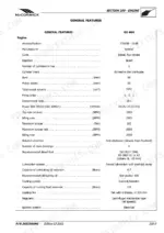
The manual provides detailed fluid specifications and capacities for various components across different GX models. For instance, the GX 40H engine lubricating oil reservoir capacity is 4.7 liters, while GX 45H and GX 50H models require 5.8 liters. The cooling fluid reservoir capacity is 2.0 liters for GX 40H and 2.7 liters for GX 45H/50H. All models use 50 liters of ISO 8217 DMA, BS 2869 A1 or A2 diesel fuel (cetane N.: 45 min). The hydrostatic transmission and power steering circuit require 18 liters of ATF Type A A suffix oil, and the front axle and front final drives need 3.5 liters of API GL 5 MIL-L-2105D EP 90 - 140 oil. p. 26
How to troubleshoot engine won't start?
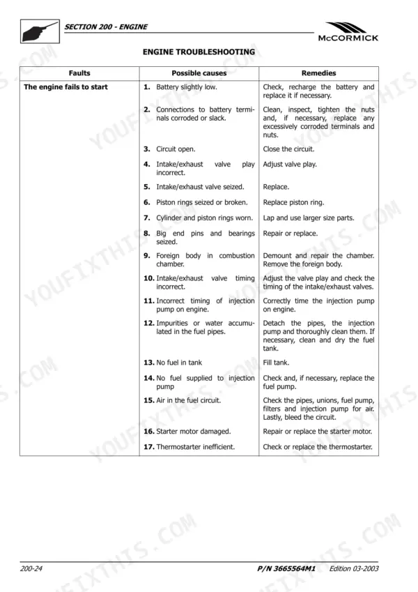
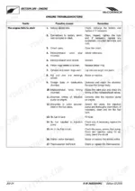
If the engine fails to start, common issues include a low battery, corroded or slack battery terminals, or an open circuit. Remedies involve checking and recharging/replacing the battery, cleaning and tightening connections, or closing the circuit. Other potential problems include incorrect intake/exhaust valve play, seized piston rings, worn cylinders, foreign bodies in the combustion chamber, incorrect injection pump timing, or air/impurities in the fuel circuit. For detailed procedures, consult page 54 of the manual. p. 54
What are the hydraulic system specifications?
The rear hydraulic power lift operates with an open center hydraulic system, using 2 single-acting cylinders with a diameter of 45 mm and a 145 mm stroke. The over-pressure valve setting is 185 ÷ 190 bar, and the cylinder safety valve is set to 200 ÷ 205 bar. The lifting capacity at ball ends with lower links horizontal is 1200 kg. Auxiliary control valves are of the standard-single/double acting, floating type with open center and quick couplings, calibrated to 185 ÷ 190 bar, and have a maximum flow rate of 28 ÷ 36 l/min. p. 293
What torque specifications are listed?
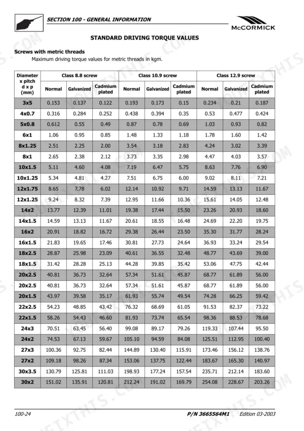
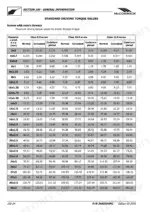
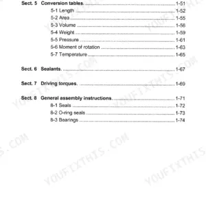
The manual lists various torque specifications for different components. For instance, screws fixing the torsional coupling to the flywheel require 23 Nm (2 ÷ 2.5 kgm), while nuts fixing the torsional joint housing to the engine need 117 ÷ 129 Nm (11.6 ÷ 13.1 kgm). Cylinder head fixing bolts are tightened to 85.3 ÷ 91.2 Nm (8.7 ÷ 9.3 kgm), and connecting rod cap fixing bolts to 44.1 ÷ 54.0 Nm (4.5 ÷ 5.5 kgm). For a comprehensive list, refer to the 'Standard Driving Torque Values' in the General Information section on page 24 and specific sections for Engine, Transmission, and other components. p. 24
What format is this manual in?
A 474-page Service Manual in searchable PDF format, available the moment you complete checkout. View on computer, tablet, or phone, with no shipping wait.
Is this McCormick GX 40H Service Manual printable?
Yes. Many mechanics print the section they need for their own shop and bring it to the bench.
Are hydraulic system diagrams in this McCormick GX 40H Service Manual?
Included. Hydraulic system schematics cover all circuits, control valves, and component specifications for the McCormick GX 40H.