
Miller service manual 48049031 is the factory shop book for the Condor GC260 and GC300 Tier 4B rear boom sprayers, and it also covers the GC300C combo. It runs long because every system has its own section, from Cummins engine removal and SCR exhaust to the foam marker.
Nothing burns a spray day like losing pressure just as the wind finally lays down. The book has the hydraulic pressure settings for both models, hydraulic schematics, electrical schematic sheets 01-22 with connector diagrams, the Cummins fault code table and the flow meter recalibration steps.
Print the sections you need and take them to the bench.
What's Inside This Miller Condor GC260, Condor GC300 Manual
| System | Pages | Key Topics |
|---|---|---|
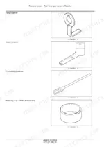
| Introduction, Safety and Capacities | 1-31 | Safety Rules, Minimum Tightening Torques, Hydraulic Torque Data, Special Tools, Tire and Rim Repair, Capacities, Product Identification |
| Engine Removal and Mounts | 32-57 | Engine Remove and Install, Engine Support and Mounts |
| Air Cleaner and Fuel System | 58-89 | Air Cleaner, Fuel-Water Separator Filter, Lift Pump, Fuel Tank |
| Engine Cooling System and Fan | 90-125 | Cooling Package, Radiator, Charge Air Cooler, Hydraulic Oil Cooler, Expansion and Deaeration Tanks, Fan, Serpentine Belt |
| SCR Exhaust Treatment | 126-153 | DOC, DEF Dosing and Supply Modules, DEF Tank and Level Lamps, SCR Muffler and Catalyst |
| Transmission and Drive Shaft | 154-185 | Allison RDS2500 and RDS3000, Ground Drive, Fluid Checks and Change Intervals, Transmission Removal, Drive Shaft |
| Front Axle and Front Wheel Assist | 186-257 | FWA Overview, Troubleshooting and Fault Codes, FWA Electrical and Hydraulic Schema, MS11 Wheel Motor, Front Axle, Suspension |
| Powered Rear Axle and Drop Box | 258-303 | Transfer Gearbox, Rear Axle, Air Bag Suspension, Sway Bar, Torque Arm, Leakage and Roll Tests |
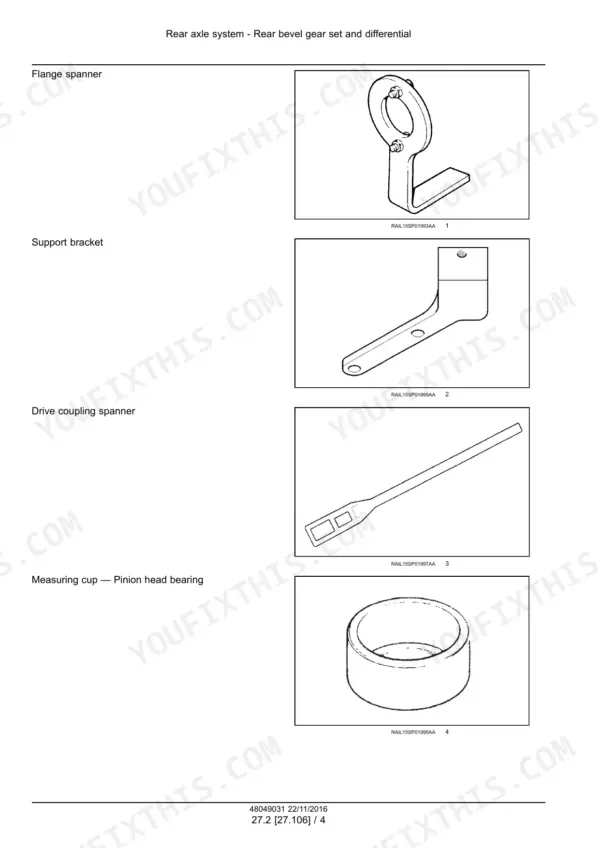
| Differential and Planetary Final Drive | 304-409 | Axle Tech and JCB Differentials, Shims and Special Tools, Pinion Seal, Planetary Final Drive, Half Shaft Bearing Carrier |
| Brakes | 410-437 | Brake Pedal Control Valve, Counterbalance Valve, Brake Accumulator Charging, Bleeding, Calipers, Parking Brake |
| Hydraulic System and Hydraulic Schematics | 438-471 | GC260 and GC300 Pressure Settings, Rear Boom Hydraulic System, Cleanliness, Hydraulic Schema Frames, Pressure Tests, Wheel Motor Startup |
| Auxiliary Pump, Reservoir and Main Control Valve | 472-499 | Auxiliary Pump, Pump Pressure Settings, Hydraulic Tank Vacuum, Reservoir, Integrated Valve Block, Check Valve |
| Pneumatic System | 500-517 | Air Compressor, Air Tank, Air Governor Adjustment |
| Towing and Ballasting | 518-535 | Vehicle Towing, Park Brake Release, Lift Accumulator Charging, Air Bag Height |
| Steering and Wheels | 536-575 | Power Steering Valve and Pressure Setting, Steering Pump, Steering Cylinder Rephasing, Front and Rear Wheels, Lug Nut Torque |
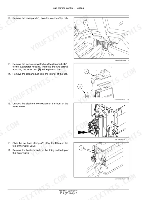
| Cab Climate Control | 576-661 | Heater Valve, Cab Filters, A/C Troubleshooting, A/C Electrical Schematics, A/C Charging, Compressor, Receiver-Dryer, Evaporator |
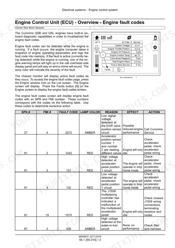
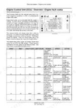
| Engine Control System and Fault Codes | 662-701 | Engine Control Unit, Cummins SPN and FMI Fault Code Table, Lamp Colors |
| Wiring Schematics and Connectors | 702-945 | Electrical Schematic Sheets 01-22, Harnesses, Connector Diagrams |
| HVAC Blowers, Starter, Alternator and Battery | 946-985 | Blower Motors, Starter, Alternator, Battery Removal |
| Sprayer Controls, Electrical System and Modules | 986-1039 | Spray Monitor Troubleshooting and Alarm Codes, Wiper, Power Distribution, Fuses and Relays, Onboard Diagnostics, CAN Bus |
| Spraying System | 1040-1075 | Spray Troubleshooting, Product Tank, Flow Meter Maintenance and Recalibration, Rinse Tank, Foam Marker |
| Accessories, Platform and Cab | 1076-1153 | Tool Box, Hood, Fenders, Ladder, Handrails, Operator Seat, Cab Roof, Console and Headliner |
Quick Reference Specifications
| Specification | Value | Page |
|---|---|---|
| Engine | Cummins QSB and QSL engines | p. 666 |
| Engine oil | NEW HOLLAND AMBRA MASTERGOLD ENGINE OIL CJ-4 SAE 10W-30; capacity: refer to Cummins manual | p. 25 |
| Coolant | NEW HOLLAND AMBRA ACTIFULL OT EXTENDED LIFE COOLANT | p. 25 |
| Transmission, GC260R | Allison RDS2500, six speed (five utilized) | p. 159 |
| Transmission, GC300R and GC300C | Allison RDS3000, six speed | p. 159 |
| Transmission normal operating sump temperature | 71 - 93 °C (160 - 200 °F) | p. 164 |
| ITL differential oil | BENZ THL-303 Hydraulic Oil or MOBIL 424, approximately 11.4 l (3 US gal) | p. 25 |
| Axle Tech limited slip differential oil | API GI-5 75W90 SYNTHETIC gear lube, approximately 7.6 l (2 US gal), plus 237 ml (8 US fl oz) limited slip additive | p. 25 |
| Drop box oil | API GL-5 85W140 gear lube, approximately 26.5 l (7 US gal) each | p. 25 |
| Planetary wheel hub oil | API GL-5 85W140 gear lube, approximately 7.6 l (2 US gal) each | p. 25 |
| A/C refrigerant | HFC-134A, 2.8 kg (6.2 lb) | p. 25 |
| Steering relief pressure (min / nom / max) | 2100 psi / 2150 psi / 2200 psi | p. 442 |
| Power steering valve setting | 148 bar (2150 psi) | p. 543 |
| Auxiliary pump pressure (min / nom / max) | 2450 psi / 2500 psi / 2550 psi | p. 442 |
| Auxiliary pump pressure, GC300 with 120 ft air boom | 2700 psi / 2750 psi / 2800 psi | p. 442 |
| Diff lock pressure setting | 350 psi / 360 psi / 370 psi | p. 442 |
| Park brake pressure setting | 1500 psi / 1500 psi / 1600 psi | p. 442 |
| Brake accumulator | 1450 psi / 1500 psi / 1550 psi | p. 442 |
| Air pressure | 110 psi / 115 psi / 120 psi | p. 442 |
| Front wheel lug nut torque | 495 N·m (365 lb ft) | p. 566 |
| Rear wheel lug nut torque, planetary drive | 434 N·m (320 lb ft) | p. 572 |
| Rear wheel lug nut torque, drop box drive | 495 N·m (365 lb ft) | p. 572 |
| Rear wheel lug nut torque, drop box with dual wheels | 569 N·m (420 lb ft) | p. 572 |
| Batteries | Two, 12 V at 925 cold cranking amps | p. 1010 |
| Foam marker relief valve | Factory set at 138 kPa (20 psi) | p. 1071 |
Miller Condor GC260, Condor GC300 Common Problems This Manual Covers
Spray pressure is reduced or lost
Work through the spraying troubleshooting pages in the Spraying system section. Start with the main product strainer and boom strainers, and look for undissolved powder. Then check the flow control valve, pump intake, impeller, monitor speed readout, ball valves and gauge. Make sure the GPS, radar or ground speed sender gives a steady speed signal. Then switch the product controller to manual and check for 12 V and ground at the product pump coil.
Manual Section: Chemical spraying - Spraying troubleshooting p. 1044Amber lamp: water detected in the fuel filter
The Engine control system and fault codes section says this lamp has no effect on performance, but don't ignore it. Drain the water from the fuel filter and check the filter wire harness. The Air cleaner and fuel system section covers the fuel-water separator filter, lift pump and fuel tank if the water keeps coming back.
Manual Section: Engine control system - Fault codes p. 667Amber lamp: diesel exhaust fluid tank below the critical warning level
Engine performance may drop once the DEF level falls below the critical warning point, so fill the diesel exhaust fluid tank before going back out. If the lamp stays on with a full tank, see the SCR exhaust treatment section. It covers the DEF tank and level lamps, the DEF supply and dosing modules, the DOC and the SCR muffler and catalyst.
Manual Section: Engine control system - Fault codes p. 679No foam from the foam marker
The Foam marker pages in the Spraying system section list four causes. The air supply may not be connected properly, the concentrate may be low, the in-line filter may be dirty or clogged, or the shut off valve may be closed. Check the air and liquid lines for holes or pinches and adjust the concentrate with the in-cab switch. Clean the in-line filter and open the shut off valve near it. The relief valve is factory set at 138 kPa (20 psi).
Manual Section: Foam marking system - Foamer system troubleshooting p. 1070Frequently Asked Questions
Which engine does the Condor GC260 or GC300 use, and what engine oil does it take?
The manual covers Cummins QSB and QSL engines, but it does not say which engine goes in which model. It gives no displacement or horsepower figures either. Engine oil is NEW HOLLAND AMBRA MASTERGOLD ENGINE OIL CJ-4 SAE 10W-30. For oil capacity, the book refers you to the Cummins manual, so keep that one nearby. p. 25
Which transmission is in the GC260 and which is in the GC300?
The GC260R runs an Allison RDS2500. It is a six speed unit with only five speeds used, and an external speed shifter motor changes gears. The GC300R and GC300C use an Allison RDS3000 six speed that shifts electronically. Both have a spring applied, hydraulic release park brake on the output shaft. Normal sump temperature is 71 - 93 °C (160 - 200 °F). p. 159
What are the hydraulic pressure settings for steering, auxiliary pump and brakes on the Miller Condor GC260 and GC300?
Steering relief is 2100 psi minimum, 2150 psi nominal and 2200 psi maximum. The power steering valve is set at 148 bar (2150 psi). Auxiliary pump pressure is 2450 to 2550 psi, with 2500 psi nominal. A GC300 with the 120 ft air boom runs 2700 to 2800 psi. The park brake is set at 1500 to 1600 psi, the brake accumulator at 1450 to 1550 psi and the diff lock at 350 to 370 psi. p. 442
How do I recalibrate the flow meter?
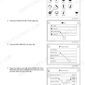
Enter a METER CAL number of 10 (38) and set TOTAL VOLUME to 0. Switch off all booms and put one boom hose into a calibrated 19 l (5 US gal) container. Switch on that boom and the MASTER switch, then pump exactly 38 l (10 US gal). The TOTAL VOLUME readout becomes your new METER CAL number. It should land within +/- 3 percent of the number stamped on the flow meter tag. Repeat the test several times and zero TOTAL VOLUME before each run. p. 1057
What torque do the wheel lug nuts need on the Miller Condor GC260 and GC300?
Front wheels have ten lug nuts torqued to 495 N·m (365 lb ft) in a star pattern. The rear wheel torque depends on the drive. Planetary drive takes 434 N·m (320 lb ft), drop box drive takes 495 N·m (365 lb ft) and drop box with dual wheels takes 569 N·m (420 lb ft). Re-torque after one hour of use. Each tire weighs about 227 kg (500 lb), so the book calls for two to three people to handle it. p. 572

Reviews
There are no reviews yet.