Part of the Case IH Repair Manuals.
This is Case IH Service Manual 48068912, 1st edition October 2016, for the Patriot 4440 Tier 4B (final) self-propelled sprayer, PIN YGT044001 and above. It walks through removing the 8.7 l Case IH Cursor engine, SCR aftertreatment, the pump drive gearbox, both axles with active suspension, and hydrostatic drive pressure tests.
The book includes electrical schematic sheets, harness and connector diagrams, fault codes with checks and fixes, and fold-out hydraulic schematics.
What's Inside This Case IH Patriot 4440 Manual
| System | Pages | Key Topics |
|---|---|---|
| Introduction | 1-39 | Cover, Product and Engine Link Table, Contents, Safety Rules, Operator Presence System, Wheels and Tires, Air-Conditioning Safety, Torque Tables, General Specification, Capacities |
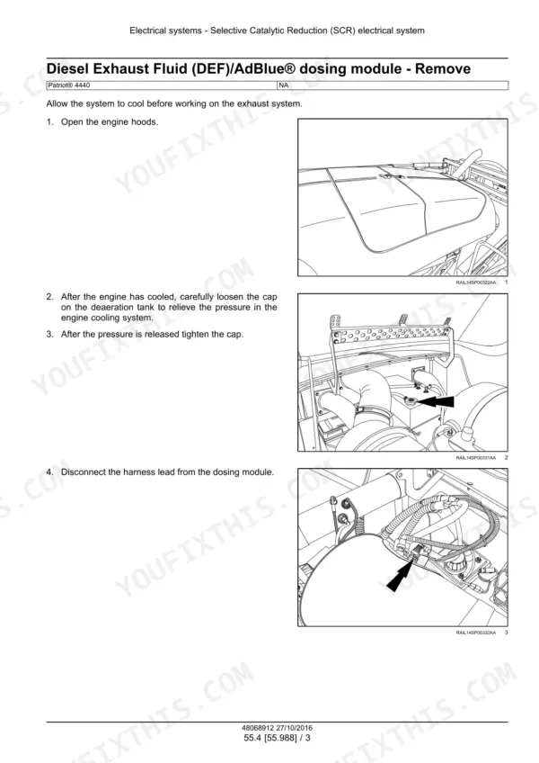
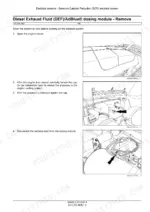
| Engine, Fuel, Air Intake and SCR | 40-129 | Engine Torques, Engine Removal and Installation, Air Filter Housing and SCR Muffler, Engine Oil Service, Fuel Tank, Air Cleaner, Fuel Filters, SCR Exhaust Treatment |
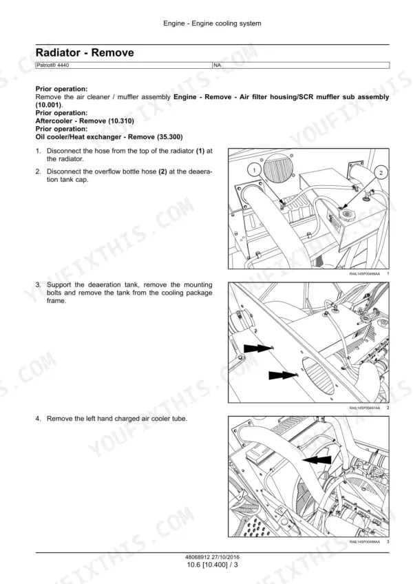
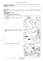
| Engine Cooling and Aftercooler | 130-151 | Radiator Removal and Installation, Aftercooler Removal and Installation |
| Power Coupling: Pump Drive | 152-169 | Hydrostatic Pump Drive Gearbox Torques, Removal, Disassembly, Assembly and Installation |
| Front Axle System | 170-239 | 4WD Axle Extension, Axle Suspension Special Tools and Torques, Active Suspension, Cylinder Overhaul, Axle Extension, Spring and Suspension Arms |
| Rear Axle System | 240-307 | Axle Adjust Cylinder, Cylinder Overhaul, Axle Extension, Spring, Upper Suspension Arm |
| Hydrostatic Drive | 308-399 | Charge Relief Valve and Pressure Control Pilot, Hydrostatic System Pressures, Drive Circuit Overview and Troubleshooting, Pump Pressure Tests, Wheel Motors |
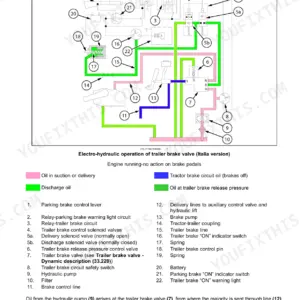
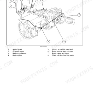
| Brakes and Controls | 400-439 | Park Brake Control Valve, Quick Disconnect, Release Procedure, Park Brake Fails to Release Test, Valve Overhaul |
| Hydraulic Systems: General and Schematics | 440-477 | Hydraulic System Pressures, Component Locations, Cylinder System Troubleshooting, Schematic Color Legend, Hydraulic Schematic Frames |
| Hydraulic Systems: Reservoir, Pumps and Cylinders | 478-543 | Oil Cooler, Hydraulic Tank, Pumps, Stabilizer, Track Widening |
| Sprayer Boom Hydraulic System | 544-599 | Boom Fold, Level, Parallel Link and Ladder Cylinder Torques, Manifold, Two-Section Valve Bank, Boom Cylinder Overview |
| Frames and Sprayer Boom | 600-677 | Sprayer Jacking Points, Inner and Outer Boom and Breakaway Torques, Sprayer Boom Removal and Installation |
| Steering | 678-731 | Power Steering Wheel, Steering Column and Tilt Release Cable, Column Overhaul |
| Wheels | 732-757 | Front and Rear Wheel Torques, Special Tools, Removal and Installation |
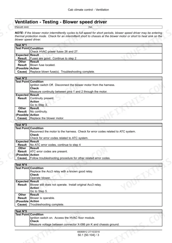
| Cab Climate Control | 758-859 | Blower Speed Driver Test, A/C Temperature and Pressure Chart, R134A Refrigerant Charge, Special Tools, Cab Pressurizing |
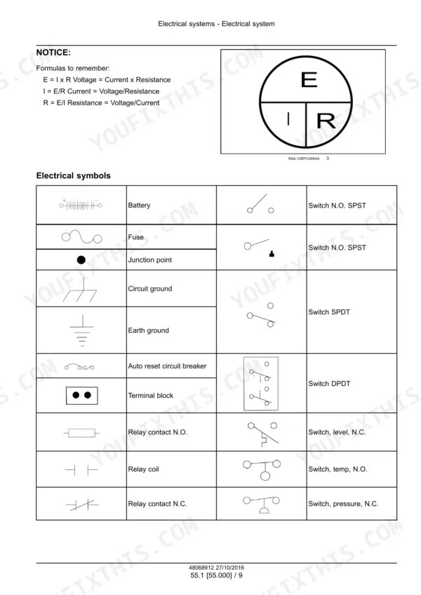
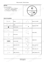
| Electrical Systems: Troubleshooting and Schematics | 860-1134 | Electrical Component Locations, General Information and Troubleshooting, Multimeter Tests, Electrical Schematic Sheets |
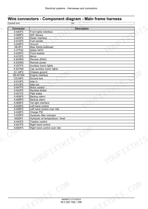
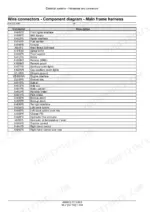
| Electrical Systems: Harness and Connector Diagrams | 1135-1575 | Component Diagrams for Main Frame, Cab, Console and Hydraulic Harnesses, Wire Connector Identification |
| Electrical Systems: Battery and Machine Controls | 1576-1695 | Battery, SCR Electrical, Hydrostatic Drive Control, HVAC Control, Wing and Boom Controls, Spray Function Controls, Product Pump PWM Valve and Driver, Boom Pressure Sensor |
| Fault Codes | 1696-2351 | Fault Code Index, ATC Codes, Seat Switch, Air Filter Clog, Engine Coolant Temperature and More, Each with Checks and Solution |
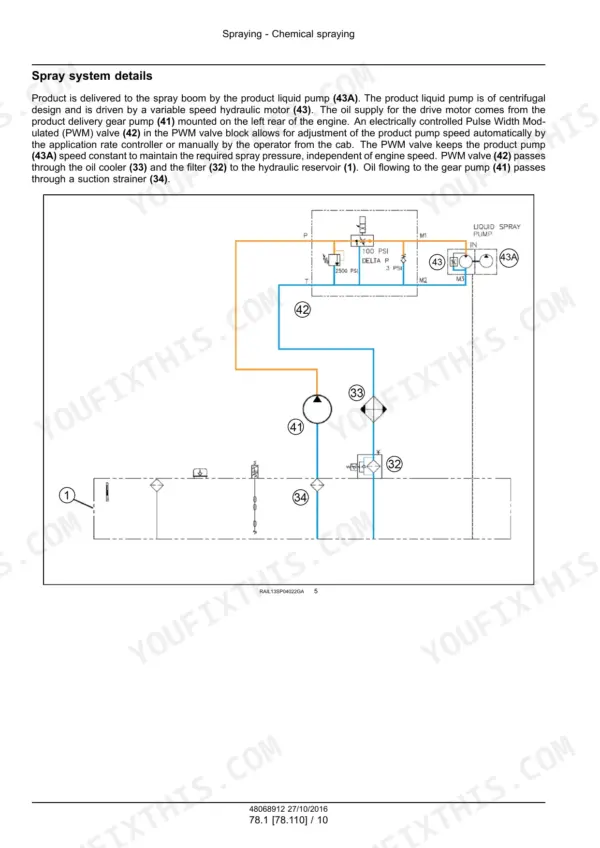
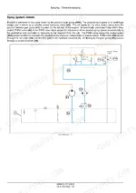
| Chemical Spraying | 2352-2469 | AIM Command and Nozzle Tip Selection, Spray System Overview, Manual Boom Height Control, AccuBoom, Filling the Rinse Tank |
| Spraying Pump and Foam Marker | 2470-2545 | Product Pump Torque, Description and Troubleshooting, Boom Pressure Sensor and Switch, Foam Marking System |
| Platform, Cab and Bodywork | 2546-2620 | Engine Hood and Shroud, Front Shield and Hood, Operator Platform Access Ladder Cylinder |
| Special Tool Index and Fold-Out Hydraulic Schematics | 2621-2627 | Special Tool Index, Fold-Out Hydraulic Schematic Sheets for the Patriot 4440 |
Quick Reference Specifications
| Specification | Value | Page |
|---|---|---|
| Engine, Case IH Cursor | 8.7 l (530 in³) | p. 35 |
| Engine oil with filter change (approximate) | 23.7 l (25.0 US qt) | p. 34 |
| Cooling system capacity | 60 l (15.75 US gal) | p. 34 |
| Radiator capacity | 30 l (7.9 US gal) | p. 34 |
| Hydraulic tank capacity | 110 l (29 US gal) | p. 34 |
| Wheel hub capacity, each | 1.1 l (2.3 US pt) | p. 34 |
| A/C refrigerant R134A capacity | 1.65 kg (3.63 lb) | p. 34 |
| Product tank size | 4542 l (1200 US gal) | p. 35 |
| Rinse tank | 530 l (140 US gal) | p. 35 |
| Foam marker tank | 208 l (55 US gal) | p. 35 |
| Dry weight (380/85 R46 tires, 90 foot boom) | 12428 kg (27400 lb) | p. 35 |
| Travel speed | Up to 48 km/h (30 mph) | p. 35 |
| Pressure compensated pump setting, 90 and 120 ft boom | 189.6 bar (2750 psi) | p. 444 |
| Pressure compensated pump flow (maximum) | 58.7 l/min (15.5 US gpm) | p. 444 |
| Auxiliary gear pump flow (maximum) | 70.8 l/min (18.7 US gpm) | p. 444 |
| Product pump circuit relief valve setting | 172.3 bar (2500 psi) | p. 444 |
| Hydrostatic working pressure | 420 bar (6090 psi) maximum | p. 346 |
| Hydrostatic charge pressure, test at 1300 RPM | 24.1 bar (350 psi) | p. 348 |
| Wheel lug nuts, front and rear | 608 - 675 N·m (450 - 500 lb ft) | p. 736 |
| Engine mount bolts | 485 - 515 N·m (358 - 380 lb ft) | p. 44 |