
Part of the New Holland Repair Manuals.
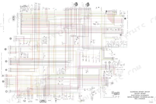
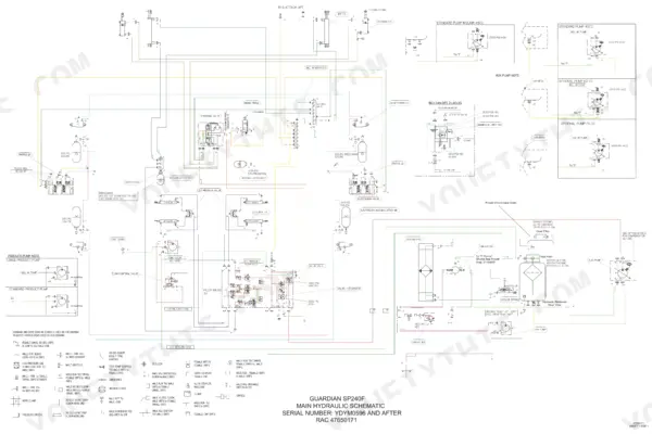
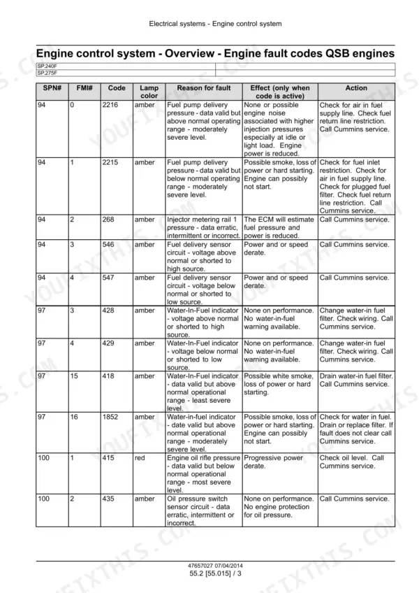
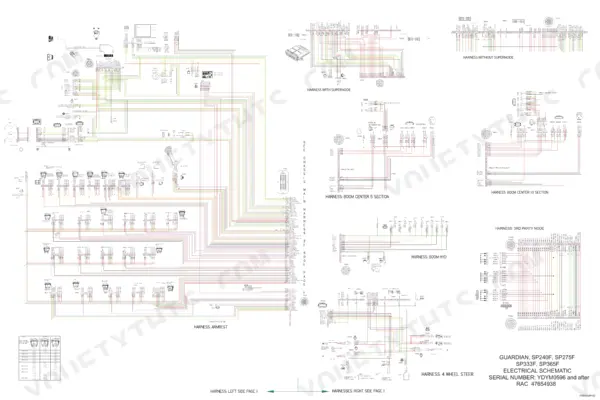
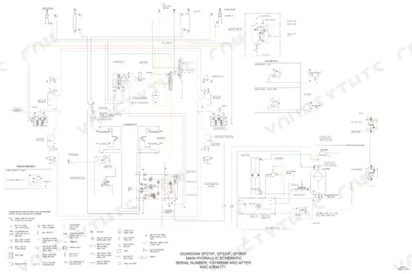
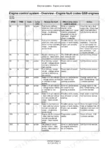
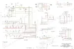
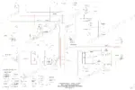
New Holland put every factory answer for its 2014 front-boom sprayers into one publication: the SP.240F, SP.275F, SP.333F, and SP.365F service manual PDF, OEM 47657027, 846 pages covering standard and Guardian versions, eight variants under a single cover. Wiring diagrams trace each harness from the engine controller through the cab to the boom, while hydraulic schematics map the machine leveling, fan drive, and auxiliary circuits line by line. Fault code tables in the electrical section turn a flashing display into a diagnosis, and the hydrostatic drive chapters carry pump and motor work from teardown through pressure testing. Charge the accumulator to 250 PSI on the 240F and 365F, hold reservoir air pressure under 34 kPa (5 psi), and set counterbalance relief at 3000 psi before you trust a loaded boom. Nobody drives out at midnight to help. You carry the answer instead: a bookmarked, text-indexed PDF that opens before the spray window does.
What's Inside This New Holland Guardian SP.240F–SP.365F Manual
| System | Pages | Key Topics |
|---|---|---|
| Introduction | 6-37 | Safety Rules, Personal Safety, General Safety Rules |
| Engine | 38-149 | Engine and Crankcase, Pump Drives, Air Cleaners and Lines, Fuel Filters, Lift Pump and Lines, Fuel Tanks, Intake and Exhaust Manifolds and Muffler, Engine Cooling System |
| Front Axle System | 150-175 | Powered Front Axle |
| Hydrostatic Drive | 176-299 | Pump and Motor Components |
| Brakes and Controls | 300-311 | Hydraulic Service Brakes |
| Hydraulic Systems | 312-391 | Auxiliary Hydraulic Pump and Lines, Reservoir, Cooler, And Filters, Machine Leveling Control System, Hydraulic Fan Drive Cooling System |
| Pneumatic System | 392-413 | Pneumatic Suspension |
| Steering | 414-473 | Steering Control, Cylinders, Hydraulic Control Components |
| Wheels | 474-491 | Front Wheels, Rear Wheels |
| Cab Climate Control | 492-571 | Heating, Ventilation, Air Conditioning |
| Electrical Systems | 572-713 | Electrical System, Engine Control System, Heating, Ventilation, And Air-Conditioning Control System, Harnesses and Connectors, Engine Starting System, Alternator |
| Spraying | 714-759 | Chemical Spraying, Spraying Pump, Foam Marking System |
| Platform, Cab, Bodywork, and Decals | 760-846 | Engine Hood and Panels, Fenders and Guards, Protections and Footboards, Mechanically-Adjusted Operator Seat, Cab, Cab Interior, Cab Interior Trim and Panels |
Quick Reference Specifications
| Specification | Value | Page |
|---|---|---|
| All Models | ||
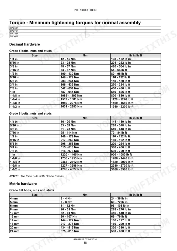
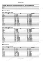
| 37° flare fitting torque (6.4 mm / 1/4 in) | 8 - 16 Nm | p. 23 |
| 37° flare fitting torque (7.9 mm / 5/16 in) | 11 - 22 Nm | p. 23 |
| Air pressure to hydraulic oil reservoir | less than 34 kPa (5 psi) | p. 216 |
| Counterbalance valve relief pressure | 211 Kg/cm² (3000 psi) | p. 464 |
| SP.240F and SP.365F | ||
| Accumulator charge pressure | 250 PSI | p. 184 |
| SP.240F | ||
| Fuel Capacity | 568 L (150 US gal) | p. 30 |
| Crop Clearance | 183 cm (72 in) | p. 30 |
| SP.275F | ||
| Fuel Capacity | 568 L (150 US gal) | p. 31 |
| Crop Clearance | 183 cm (72 in) | p. 31 |
| SP.365F | ||
| Fuel Capacity | 568 L (150 US gal) | p. 32 |
| Crop Clearance | 183 cm (72 in) | p. 32 |
| SP.333F | ||
| Fuel Capacity | 568 L (150 US gal) | p. 34 |
New Holland Guardian SP.240F–SP.365F Common Problems This Manual Covers
New Holland Guardian SP.275F wheel motor leaking oil at the hub, hydraulic film coating the inside of the rim
Clean the wheel end, then run the machine and watch where the leak starts. Check charge pressure per the chart on page 290: MW14 motors should hold 30 bar (435 psi) with no more than a 6 bar (85 psi) drop under load. Verify the case drain circuit is flowing free before you replace the shaft seal, because high case pressure will blow the new seal too.
Manual Section: Hydrostatic Drive p. 290Boom free-falls during unfolding after a hydraulic hose blowout near the fold cylinder
Relieve all boom circuit pressure and set the boom on stands before touching a fitting. Replace the failed hose plus any neighbor showing cover wear from rubbing. Torque 12.7 mm (1/2 in) 37 degree flare fittings to 20 - 57 N·m using the chart on page 23, then reroute and clamp the hoses clear of the over-center pivot so they stop sawing themselves in half.
Manual Section: Hydraulic Systems p. 312Hydrostatic drive stalls climbing hills with a half tank of product, engine still holds RPM
Test hydrostatic loop pressure under load on a grade; the high pressure relief is set at 448 bar (6500 psi) per page 290. If pressure tops out well below that before the machine quits pulling, suspect a pump or wheel motor bypassing internally. Check charge pressure during the same pull, since a starved charge circuit kills the loop before the hill does.
Manual Section: Hydrostatic Drive p. 290Rear steer wanders or corrects late on side hills, steering wheel input feels normal
Inspect the autosense harness and connectors at the rear axle for chafe, corrosion, and loose pins before condemning the hydraulics. Test the counterbalance valve; relief should be 211 kg/cm² (3000 psi) as noted on page 464. Cycle the steering lock to lock, watch for cylinder drift, and recalibrate the steering sensors after any repair so the rear axle tracks true again.
Manual Section: Steering p. 464Front wheel lug nuts work loose after tread width adjustment, wheels click on turns
Remove each loose nut, inspect the studs and wheel pilot for elongation or thread damage, and clean the mating faces to bare metal. Torque the lug nuts in a cross pattern to 610 N·m (450 lb ft) per page 480. Recheck torque after the first trip across the field, because freshly adjusted mounts settle and give up clamp load fast.
Manual Section: Wheels p. 480Frequently Asked Questions
What are the torque specifications for the wheel lug nuts on the SP.240F, SP.275F, SP.333F, and SP.365F?
The wheel lug nuts must be torqued to 610 N·m (450 lb ft). This should be done in a star-patterned sequence, and the lug nuts must be re-torqued to the same value after 1 hour of use. p. 479
What is the procedure for clearing error codes on the ATC control panel?
To enter the error code mode, turn the system on and press the PWR and AUTO keys simultaneously. You can scroll through multiple errors by repeatedly pressing the PWR key. The system will automatically exit the error code mode after five seconds. p. 522
What is the correct hydraulic pressure setting for the auxiliary pump on the SP.240F?
The nominal pressure setting for the auxiliary pump on the SP.240F is 2500 psi. The minimum is 2450 psi and the maximum is 2500 psi. p. 315
What is the required torque for the valving mounting screws on the hydrostatic wheel motor of a New Holland Guardian SP.240F–SP.365F sprayer?
The valving mounting screws on the hydrostatic wheel motor must be torqued to 320 - 390 N·m (236 - 288 lb ft). p. 236
What is the correct procedure for bleeding air from the wheel motor after service?
Two people are required for this procedure. With the engine running at low idle, apply the foot brake and hold it. Loosen the bleed set screw (4) on the XD port 1 to 1-1/2 turns counterclockwise until the oil flow is free of air bubbles, then tighten the set screw. p. 216
What do I get after purchasing this New Holland SP.240F manual?
All 846 pages arrive as one searchable PDF at checkout. Read it at the desk, then take the phone out to the machine.
Can I print a copy of this New Holland SP.240F Service Manual for the shop?
Yes. No DRM, nothing blocks printing, so run off the pages you need on whatever printer you have.





Reviews
There are no reviews yet.