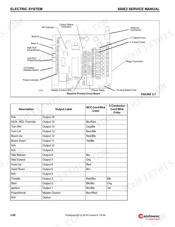
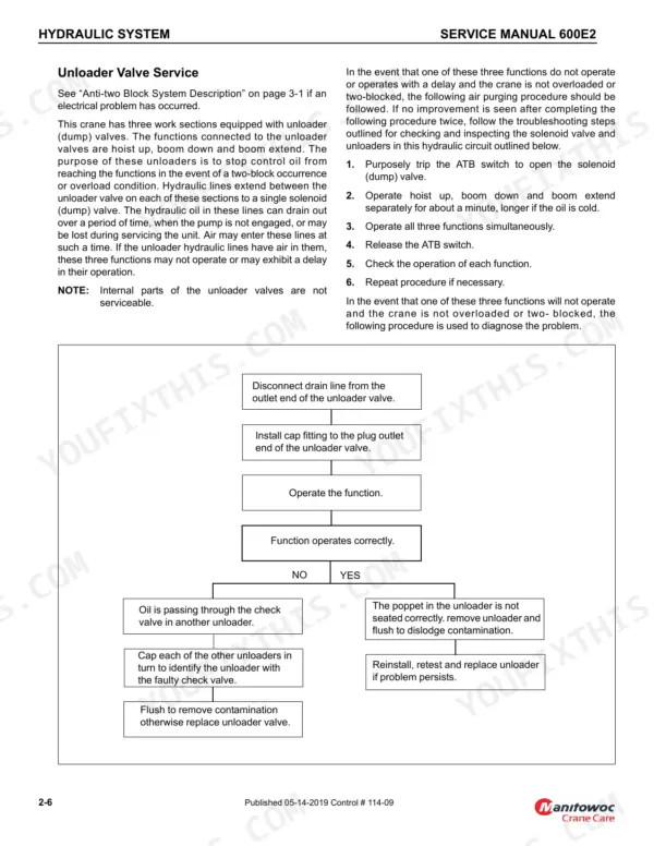
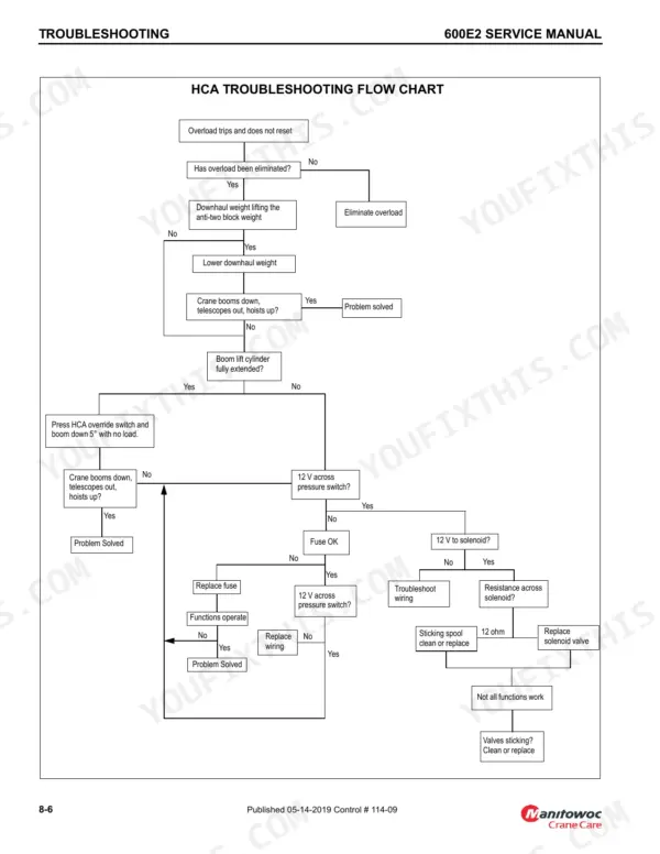
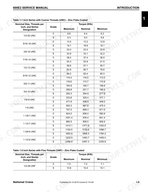
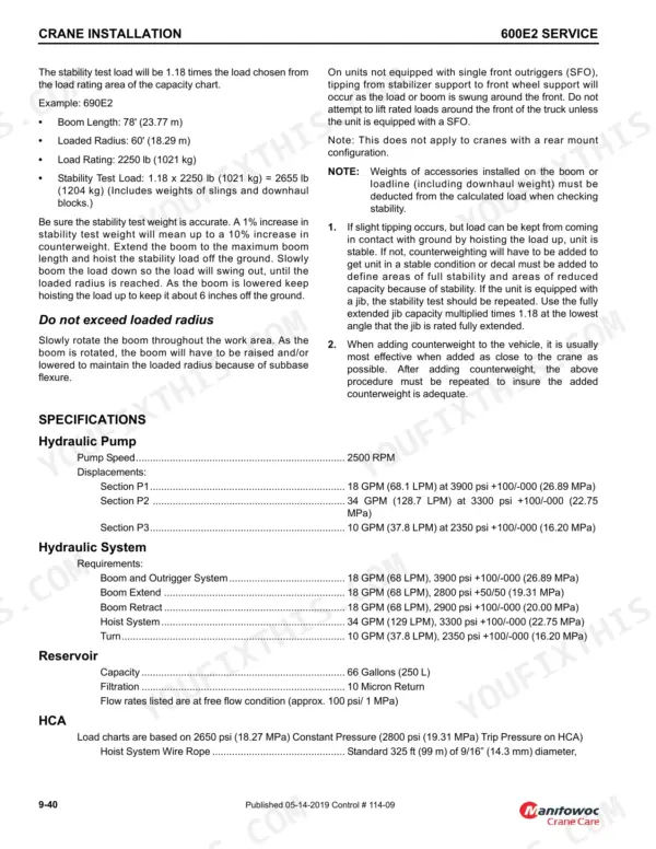
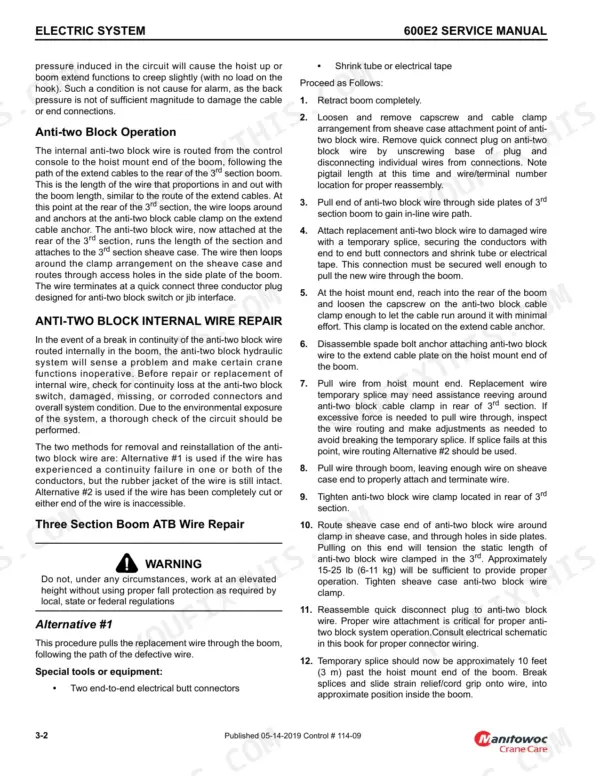
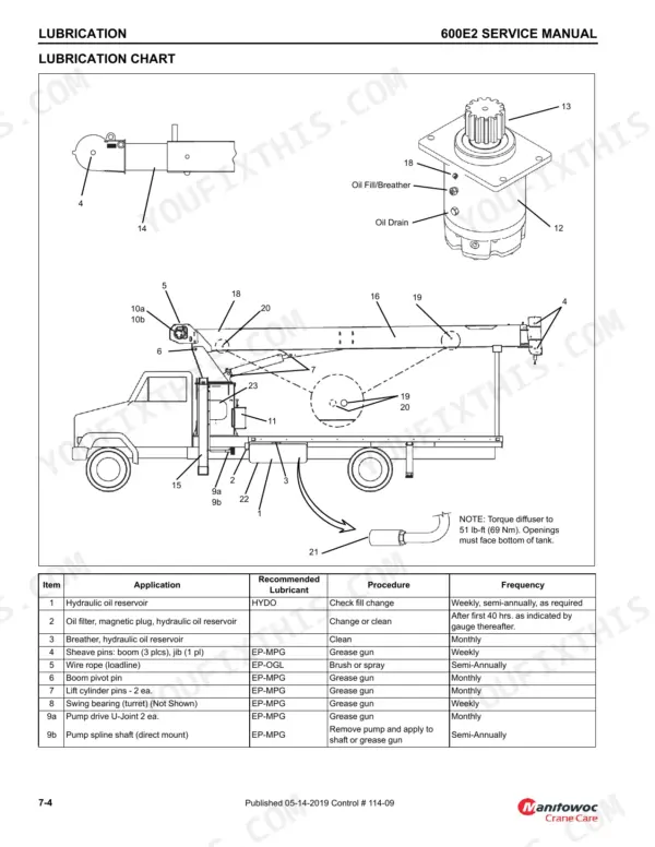
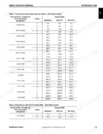
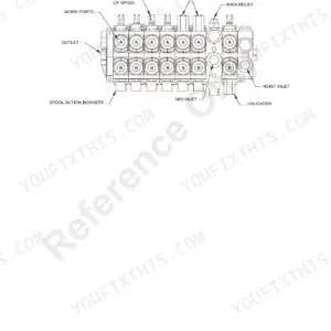
Built around the National Crane 600E-2, 647E2 and 638E2 cranes, this 184-page service manual PDF (OEM publication 114-09) fits all three models, with mounting configurations called out for each. Hydraulic and electrical schematics close the book, tracing circuits from the control valves and unloader through anti-two block, HCA and outrigger monitoring wiring, while the troubleshooting chapter pairs a hydraulic system chart with an HCA flow chart. Truck installation fills close to a quarter of the pages: frame section modulus tables, PTO horsepower requirements, counterweighting methods and CAN bus setup. Check swing bearing clearance against the 0.090 in limit, and torque wear pad retainer capscrews to 110 ft-lb (149 N-m). Guess a pad thickness, and you pull the boom twice. Bookmarks take you straight to each chapter, and the pages print clean enough to sit on your bench and soak up hydraulic oil.
What's Inside This Manual
| System | Pages | Key Topics |
|---|
| Introduction | 11-34 | General (Supplemental Information, New Owner, Cleanliness) |
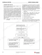
| Hydraulic System | 35-42 | Hydraulic System Description (Hydraulic System Maintenance Precautions, Label Parts When Disassembling, Hydraulic Oil Recommendations) |
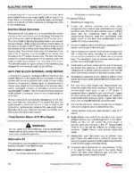
| Electric System | 43-74 | Anti-Two Block System Description, Anti-Two Block Operation |
| Boom | 75-100 | Three Section Boom Operation (Special Boom Inspection), Three Section Boom Maintenance (Three Section Cable Tensioning), Hoist Removal, Boom Removal |
| Hoist | 101-102 | Hoist Removal, Hoist Installation |
| Swing | 103-116 | Swing Gearbox and Brake (Disassembly and Assembly Instructions, Swing Drive Disassembly, Tulsa Swing Drive Assembly Procedure), Rotation Stop-Mechanical (Rotation Stop Adjustment) |
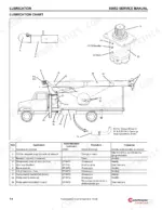
| Lubrication | 117-130 | General (Surface Protection for Cylinder Rods, Lubricants, Arctic Conditions Below 0°F) |
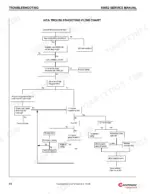
| Troubleshooting | 131-136 | Hydraulic System Troubleshooting Chart, Jib Load Limiting Device Troubleshooting, Jib Jack Troubleshooting (Systematic Troubleshooting), HCA Troubleshooting Flow Chart |
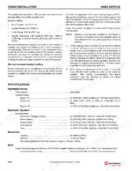
| Crane Installation | 137-178 | Crane to Truck Installation, Minimum Truck Requirements |
| Schematics | 179-184 | Hydraulic Schematics, Electrical Schematics |
Quick Reference Specifications
| Specification | Value | Page |
|---|
| Solenoid resistance | 12 ohm | p. 136 |
| Top rear pad thickness | 0.75 inch (19.05 mm) | p. 81 |
| Bottom front 1st section pad thickness | 1 inch (25.4 mm) | p. 81 |
| Torque for Second Nut (Metric Series) | M16x2: 26 Nm, M20x2.5: 66 Nm | p. 95 |
| Swing bearing clearance limit | 0.090 in | p. 111 |
| Swing drive pinion backlash shim thickness | 0.008 in (0.203 mm) | p. 114 |
| Slew pot gear to swing bearing gear teeth gap | 0.125 - 0.188 in (3.1 - 4.7 mm) | p. 115 |
| Hoist brake fill capacity | 0.23 liter (0.25 quart) | p. 123 |
| Motor counterbalance valves setting | 600 psi | p. 132 |
| Main Relief Valve Adjustment (Crane Valve) | 32 ft-lb (43 Nm) | p. 39 |
| Main Relief Valve Adjustment (Hoist Valve) | 25 ft-lb (34 Nm) | p. 39 |
| Hoist Gearbox Oil Capacity | 1.42 liters (1.50 quarts) | p. 124 |