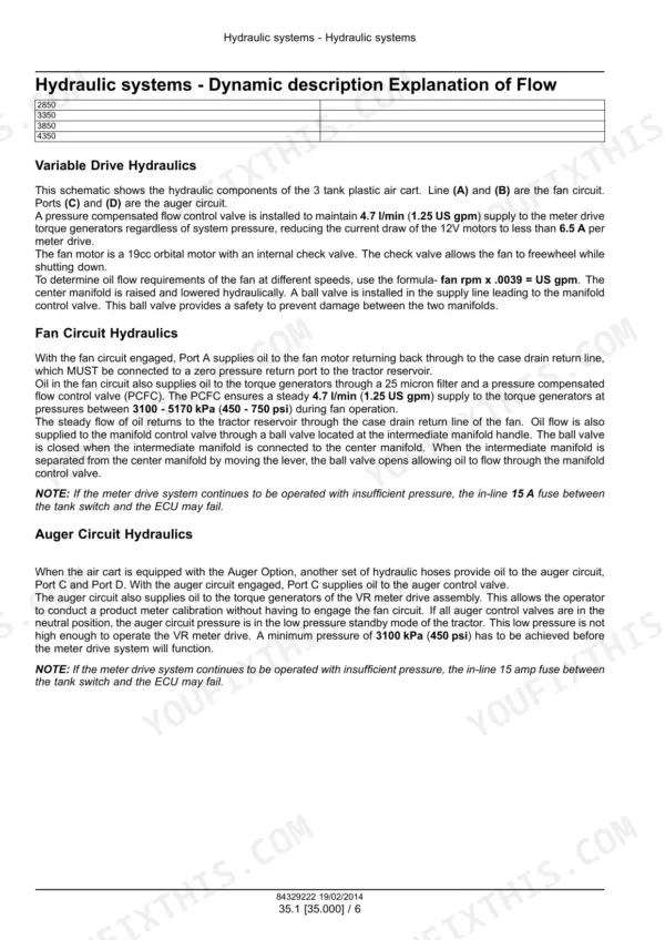
This is the factory service manual for the Flexi-Coil 1740, 2340, 2850, 3350, 3850 and 4350 air carts, and it covers the whole machine, not just the iron. You get the seeding and fan hydraulic circuits with real test values (the fan runs a 19cc orbital motor with an internal check valve, and the PCFC feeds the torque generators at 4.7 l/min between 3100 and 5170 kPa), full wire harness schematics by circuit, ECU and rate controller diagnostics, a fault code listing with causes and troubleshooting steps, plus the metering drive, air distribution, rear axle, wheels, lighting and auger wiring. If your cart throws a code or stops metering, the answer is in here.
Other edition of this manual
- Flexi-Coil 3450, 2340, 1740, 2640, 3850, 4350 Air Cart Service Manual (incl. Wiring) Original price was: $56.99.$39.99Current price is: $39.99.
What's Inside This Flexi-Coil 1740–4350 Manual
| System | Pages | Key Topics |
|---|---|---|
| Introduction | 1-87 | Contents, Safety Rules, Safety Signs, Hand Signals, Torque Reference, Electrical Testing Basic Instructions, Product Identification |
| Rear Axle System | 88-105 | Non-Powered Rear Axle |
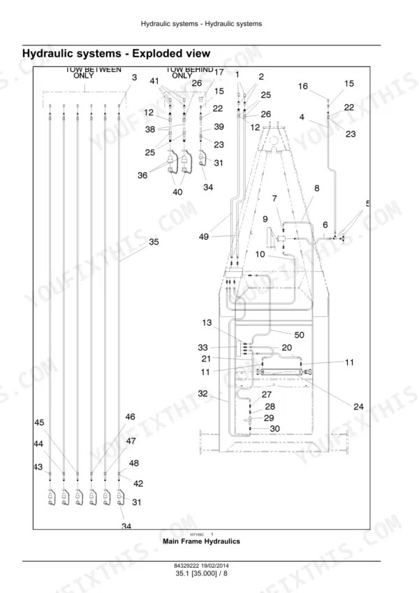
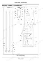
| Hydraulic Systems | 106-203 | Reservoir Cooler and Filters, Seeding Hydraulic Circuit, Metering System Hydraulic Circuit, Hydraulic Seeding Fan System, Main Frame Hydraulics |
| Wheels | 204-225 | Rear Wheels, Caster Wheels |
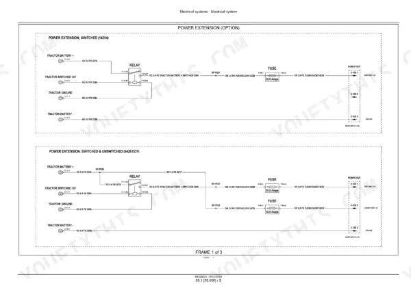
| Electrical System (General) | 226-238 | Electrical Schematic Frames, Tractor Harness Power Extension and CAN Bus |
| Harnesses and Connectors | 239-432 | Wire Harness Schematics by Circuit (Lighting, Tank Level and Low Sensors, Meter RPM, Meter Air Speed, ECU Connections) |
| Alternator | 433-446 | Alternator Testing and Wiring |
| External Lighting | 447-468 | Warning Lights, Tail Lights, Transport Lighting |
| Seeding Control System | 469-576 | Rate Controller, ECU, Optical and Ultrasonic Tank Sensors, Flow Monitoring |
| Cab Seeding Controls | 577-624 | In-Cab Display and Control Wiring |
| Auger | 625-638 | Auger Control Wiring |
| Electronic Modules | 639-644 | ECU and Module Identification |
| Split Meter Control System | 645-658 | Split Meter Drive Control Wiring |
| Fault Codes | 659-1097 | Diagnostic Trouble Code Listing by SPN-style Code (Example 520203-03 and 520199-04), Cause and Troubleshooting Steps for Rate-Control ECUs |
| Metering System | 1098-1183 | Split Meter Control System, Metering Mechanical Drive, Product Metering |
| Seeding | 1184-1288 | Product Handling and Delivery Drive System, Seeding Fan System, Air Distribution System |
| Special Tool Index | 1289-1290 |
Quick Reference Specifications
| Specification | Value | Page |
|---|---|---|
| Fan circuit flow to torque generators (pressure compensated flow control) | 4.7 l/min (1.25 US gpm) at 3100-5170 kPa (450-750 psi) | p. 112 |
| Auger circuit minimum pressure to run VR meter drive | 3100 kPa (450 psi) | p. 112 |
| In-line fuse between tank switch and ECU | 15 A | p. 112 |
| Fan motor | 19cc orbital motor with internal check valve | p. 112 |
Flexi-Coil 1740–4350 Common Problems This Manual Covers
Low voltage alarms from the electronic control system
The Electronic control problem solving section on page 566 tells you to compare the reading against tractor battery voltage. When the voltage at the module is lower than battery voltage, check the harness for damage or disconnection, working the circuit back with the harness schematics.
Manual Section: Electronic control - Problem solving Low voltage alarms p. 566Code 211, optical sensor shorted to high source
Page 904 covers this code directly. Before replacing anything, inspect the optics of the sensor for coatings of dust or other debris and clean using mild soap and water if required. Seed treatment dust on the lens sets this code far more often than a bad sensor.
Manual Section: 211-Optical sensor shorted to high source Optical Sensors p. 904Flow monitor showing blocked or low flow runs
The Flow monitoring troubleshooting section on page 572 says openers may be plugged or worn out, so inspect openers for wear and replace if necessary, and primary hoses may be plugged, so check primary hoses for blockages before condemning the monitor itself.
Manual Section: Flow monitoring - Troubleshooting p. 572Cart will not meter product even though the drive turns
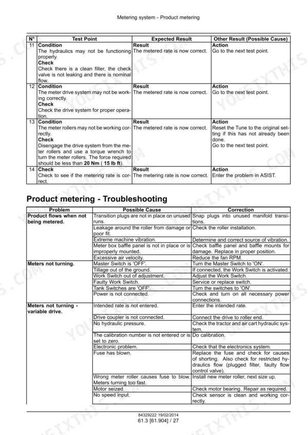
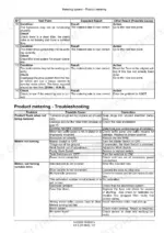
The Product metering troubleshooting table on page 1177 flags a setup miss most owners overlook: the calibration number is not entered or is set to zero. The fix is to do the calibration procedure, which the metering system section lays out step by step.
Manual Section: Product metering - Troubleshooting p. 1177Frequently Asked Questions
The display says the intended rate is not entered and the cart will not meter. What does the manual say?
That exact message is covered in the Product metering troubleshooting table on page 1177. The fix is what it sounds like: the intended rate was never keyed in, so enter the intended rate. The same table walks you through the other no-meter causes so you are not guessing in the field. p. 1177
Why does my air cart show a low hydraulic pressure warning?
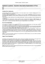
Page 126 in the hydraulic systems troubleshooting section lists the real causes: the tractor hydraulics are not engaged, fan speed is too low, or the fan is rotating in the wrong direction. That last one bites people after a hose swap. The manual takes you through each check in order. p. 126
What do the fault codes on the rate control ECUs actually mean?
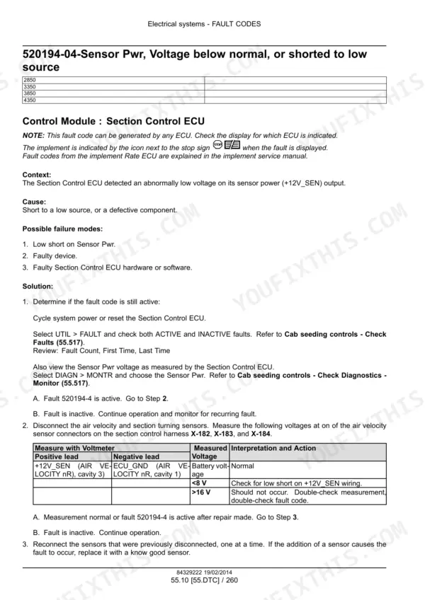
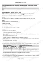
The FAULT CODES section lists diagnostic trouble codes with cause and troubleshooting steps for each. For example, page 918 explains the code set when the Section Control ECU detects abnormally low voltage on its +12V_SEN sensor power output, then tells you where to test. Codes are listed in SPN style, like 520203-03 and 520199-04. p. 918
My rate control hunts and will not settle. Can I fix that without a dealer?
Yes. The Seeding control system section, page 473, says adjustments to the Tune setup to improve controller responsiveness, or changing the implement speed to adjust meter RPM, may be necessary. The manual explains the dynamic behavior of the controller so you know which knob to turn. p. 473
How much hydraulic pressure does the auger circuit need before the VR meter drive will run?
Page 112 gives the number: 3100 kPa, which is 450 psi minimum in the auger circuit to run the variable rate meter drive. Below that the drive simply will not go, and people chase electrical ghosts when the problem is a tired hydraulic supply. p. 112