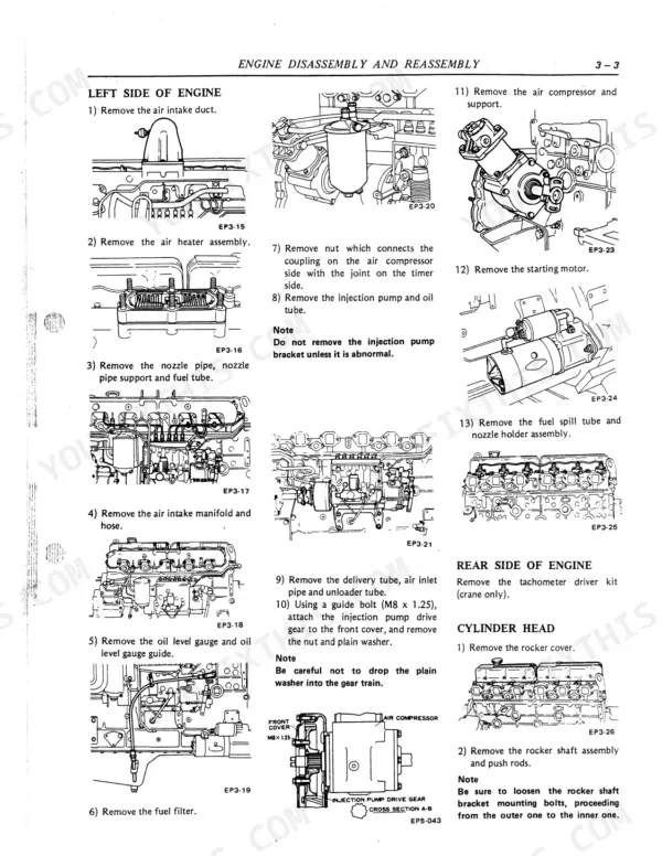
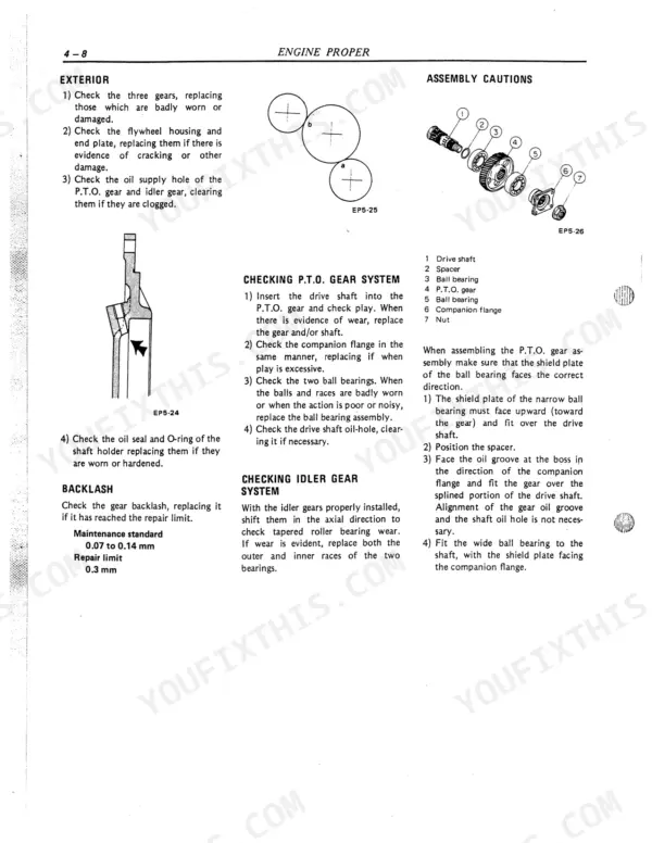
This is the factory service manual for the Nissan Diesel PE6 and PE6T engines, publication number 8906261-16834-300-KSS. It is a 224 page PDF that downloads instantly and opens on a phone, tablet, or shop computer.
The manual is a full engine overhaul reference: general data, disassembly judgment and troubleshooting, complete engine disassembly and reassembly, the cylinder head and valve mechanism, lubrication, cooling, the fuel injection system, air intake and exhaust with the turbocharger, the electrical system, engine test procedures, and service data tables with maintenance standards and tightening torques.
With it you can diagnose hard starting, overheating, low oil pressure, or smoke, then measure, adjust, and rebuild to the listed limits yourself. Print the pages you need or keep the whole file on hand in the shop.
What's Inside This Nissan Diesel Motor Co., Ltd. PE6, PE6T Manual
| System | Pages | Key Topics |
|---|---|---|
| General | 12-17 | Method of Using This Manual, Standardization of Terms, Engine Position, Abbreviation, Maintenance Standard, Wear Limit, Repair Limit, Units |
| Disassembly Judgment | 18-27 | Determining the Need for Engine Overhaul, Troubleshooting Tests, Cause of Trouble and Its Correction, Diagnosis Guide |
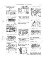
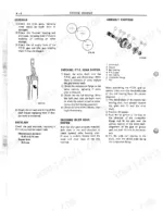
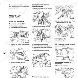
| Engine Disassembly and Reassembly | 28-39 | Disassembling Engine (Turbocharger, Right Side of Engine, Front Side of Engine, Left Side of Engine, Rear Side of Engine, Cylinder Head, Engine Proper, Engine Rear P.T.O.) |
| Engine Proper | 40-51 | Adjustment, Cleaning, Inspection, Repair and Replacement |
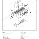
| Cylinder Head and Valve Mechanism | 52-59 | Disassembly and Cleaning, Inspection, Repair and Replacement, Reassembling |
| Lubrication System | 60-66 | Lubricating System Diagram, Oil Pump, Oil Cooler, Oil Filter |
| Cooling System | 67-75 | Cooling System Diagram, Water Pump, Thermostat, Radiator and Water Tank, Fan and Fan Drive |
| Fuel System | 76-89 | Fuel Injection Pump (Separating Each Component, Boost Compensator, Injection Pump Proper, Installing Each Component, Fuel Feed Pump and Priming Pump, Type Rq Limit Speed Governor, Type Rfd Mechanical Governor, Timer) |
| Air Intake and Exhaust System | 90-99 | Nozzle and Nozzle Holder, Fuel Filter and Overflow Valve, Turbocharger, Air Cleaner |
| Electrical System | 100-110 | Adjusting and Testing Injection Pump, Exhaust Shutter, Air Cylinder, Starting Motor |
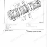
| Auxiliary Equipment | 111-124 | Regulator, Air Heater, Air Compressor, Power Steering Oil Pump |
| Engine Test Procedures | 125-128 | Measurement of Compression Pressure, Valve Timing Measurement, Fuel Injection Timing Measurement, Engine Performance Test Methods |
| Service Data | 129-144 | Maintenance Standard Tables, Tables of Tightening Torque |
| Tools | 145-224 | Special Tools (Engine Disassembly and Reassembly, Engine Proper, Cylinder Head and Valve Mechanism, Lubrication System, Cooling System, Fuel System, Air Intake and Exhaust System, Auxiliary Equipment, Engine Test Procedures) |
Quick Reference Specifications
| Specification | Value | Page |
|---|---|---|
| Cylinder head bolt tightening torque (1st time) | 15.0 to 16.0 kgm | p. 47 |
| Cylinder head bolt tightening torque (2nd time) | 22.0 to 23.0 kgm | p. 47 |
| Fuel filter case center bolt tightening torque | 2.0 - 3.0 kgm | p. 218 |
| Nozzle nut tightening torque | 6 to 8 kgm | p. 120 |
| Injection start pressure | 200 kg/cm² | p. 121 |
| Delivery valve holder tightening torque | 11.0 to 12.0 kgm | p. 106 |
| Camshaft end play repair limit | 0.50 mm | p. 108 |
| Valve opening temperature maintenance standard | 76.5°C | p. 91 |
| Valve opening temperature wear limit | 75.0 to 78.0°C | p. 91 |
| Fit of shaft and impeller maintenance standard | 0.04T to 0.07T mm | p. 90 |
| Water pump gear nut tightening torque | 6.0 to 7.0 kgm | p. 91 |
| Intake valve stem outside diameter nominal dimension | 11.97 to 11.98 mm | p. 75 |