
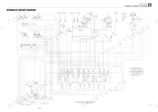
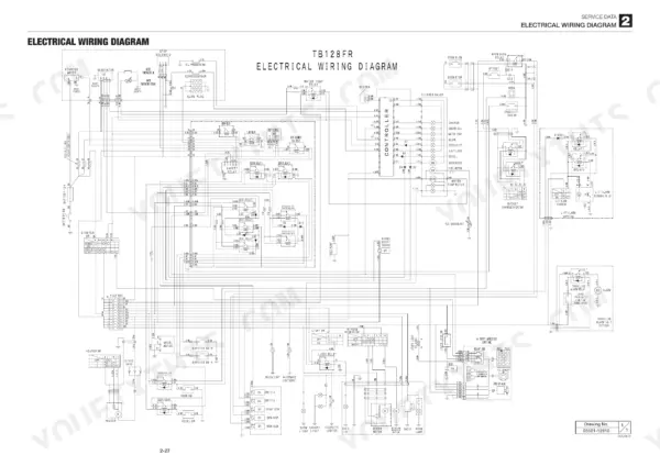
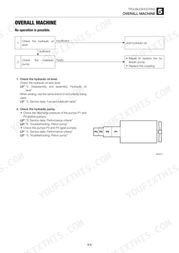
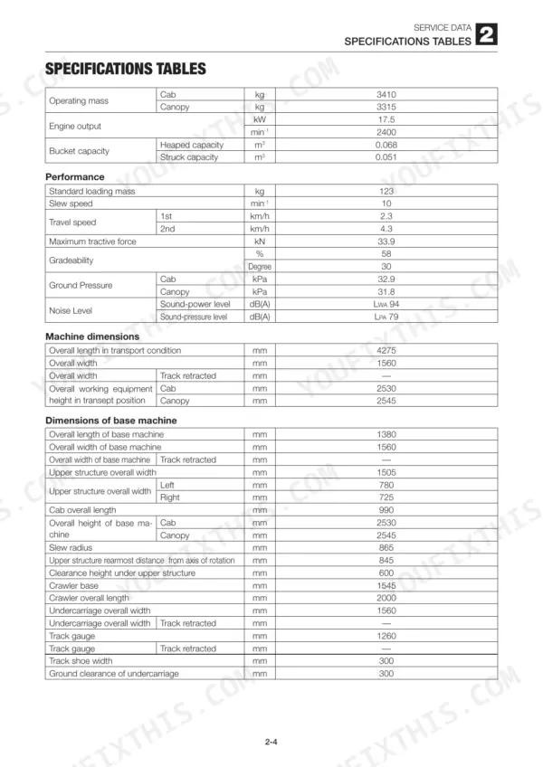
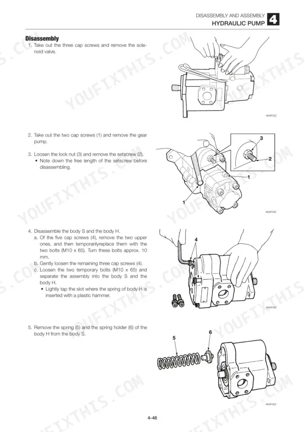
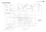
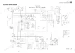
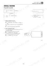
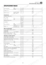
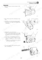
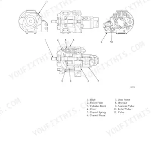
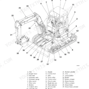
Wondering what's in a Takeuchi TB128FR shop manual PDF? All 287 pages here cover one machine: the TB128FR mini excavator, from crawler belt to slew bearing. You get the complete hydraulic circuit diagram, electrical wiring and wire harness diagrams, plus step-by-step disassembly and assembly for the piston pump, control valve, pilot valves, cylinders, travel motor, slew motor, and swivel joint. A full troubleshooting section walks you through every failure mode: no operation, weak slew, spontaneous boom drop, a dead offset cylinder, even the interference prevention system. Set rubber track tension at 77 to 87 mm and torque the track roller bolts to 158 N·m; the hydraulic tank holds 44 L and the system takes 70 L of oil in total. No more chasing a lazy boom with guesswork. Bookmarked chapters and a real text layer let you jump straight to any spec, on any device, right at the machine.
What's Inside This Takeuchi TB128FR Manual
| System | Pages | Key Topics |
|---|---|---|
| Safety | 3-12 | Safety Alert Symbol, Safety Precautions, Cautions When Working |
| Service Data | 13-46 | Dimensional Drawing, Specifications Tables, Lubricant and Fuel Chart, Performance Criteria, Tightening Torque, Hydraulic Circuit Diagram, Electrical Wiring Diagram |
| Function | 47-82 | Piston Pump Discharge Control Mechanism, Relief and Solenoid Valve Operation, Control Valve Circuit Pressures, Boom Lower Operation, Counterbalance Valve, Travel 2-Speed Mechanism, Slew Relief and Make-Up Valves, Anti-Rebound Timer Valve, Interference Prevention Logic, Attachment Interference Switch |
| Service Standards | 84-86 | Carrier Roller, Track Roller, Drive Sprocket, Idler, Pin and Bushing Clearance |
| Drive System | 87-93 | Engine, Radiator, Oil Cooler, Hydraulic Pump, Fuel Tank, Throttle Lever |
| Travel System | 94-98 | Crawler Belt, Steel Crawler, Carrier Roller, Track Roller, Idler, Track Adjuster, Travel Motor |
| Slew System | 99-101 | Slew Motor, Slew Bearing, Swivel Joint, Brake Valve |
| Upper Frame | 102-107 | Floor Frame, Covers, Cab |
| Control System | 108-115 | Control Lever, Blade Lever, Lever Stand, Control Cable |
| Attachments | 116-121 | Bucket, Bucket Link, Arm, Boom, Boom Bracket, Dozer Blade |
| Hydraulic Tank | 122-126 | Hydraulic Oil Tank, Sight Gauge, Return Filter, Suction Filter, Valve Assembly |
| Hydraulic Pump | 127-135 | Piston Pump, Gear Pump, Cylinder Block, Swash Plate, Shoe Holder, Valve Plate, Shaft Assembly, Oil Seal, Spring Guide |
| Control Valve | 136-146 | Tie Rod, Bucket Section, Boom Section, Arm Section, Left and Right Travel Sections, Switch Valve, Main Relief Valve, Load Check Valve, Pilot Operated Section |
| Pilot Valve | 147-153 | Spool, Push Rod, Spring Seat, Spring, Washer, Plug, O-Ring and Seal, Joint Disc, Special Tools |
| Pilot Valve (Offset) | 154-157 | Cover, Boot, Plug, Spool Assembly, Spring, O-Ring and Seal |
| Pilot Valve (Travel) | 158-162 | Orifice, Shim, Washer, Push Rod, Balls and Holders, Plugs, Boot, Cover |
| Solenoid Valve | 163-166 | Pressure Reducing Valve, Coil, Spool, Sleeve, Shim, Spring, Plug, Body |
| Cylinders | 167-181 | Boom Cylinder, Arm Cylinder, Bucket Cylinder, Offset Cylinder, Rod Packing, Dust Seal, Wear Ring, Piston Packing, Bushing, No-Load Operation Test |
| Travel Motor | 182-205 | Hydraulic Motor, Counter Balance Valve, 2nd Speed Mechanism, Reduction Gears, Brake Valve |
| Slew Motor | 206-220 | Hydraulic Motor, Relief Valve, Make-Up Valve, Anti-Rebound Valve, Parking Brake, Reduction Gears |
| Swivel Joint | 221-225 | Shaft, Hub, Flange, Thrust Ring, Slipper Seal, O-Ring |
| Interference Prevention System | 226-228 | Interference Sensors, Boom Switches, Offset Switch, Attachment Interference Switch, Solenoid Valve, Interference Prevention Relay |
| Troubleshooting | 229-286 | Overall Machine (No Operation Is Possible., All Systems Working, But Insufficient Force., Boom, Bucket, Slew and Arm Fail to Move or Are Too Slow.) |
| Engine | 287 | Machine Model, Mounted Engine |
Quick Reference Specifications
| Specification | Value | Page |
|---|---|---|
| Track tension (Rubber) | 77 to 87 mm | p. 24 |
| Track roller fixing bolt torque | 158 N·m | p. 95 |
| Engine cushion rubber bolt torque | 102 N·m | p. 86 |
| Engine Output | 17.5 kW | p. 16 |
| Operating Mass (Cab) | 3410 kg | p. 16 |
| Hydraulic Tank Capacity | 44 L | p. 21 |
| Hydraulic Oil, Total Amount (system) | 70 L | p. 21 |
| Engine Coolant Capacity | 4.3 L | p. 21 |
| Fuel Tank Capacity | 39 L | p. 22 |
| Main Relief Valve Pressure | 21.0 MPa | p. 25 |
| Pilot Pressure | 3.4 MPa | p. 25 |
| Engine Oil Pan Capacity (Upper limit) | 3.6 L | p. 21 |
Takeuchi TB128FR Common Problems This Manual Covers
Takeuchi TB128FR hydraulic functions weak and slow, boom and arm barely lift under load
Check the hydraulic oil level on the sight gauge first; the tank holds 44 L and low oil starves the pump. Test main relief pressure against the 21.0 MPa spec listed on page 25. If pressure is low, work through the insufficient force chart starting before condemning the pump.
Manual Section: Overall Machine p. 232Whole machine dead, no travel or boom response even with engine running normal
Verify pilot pressure before tearing anything apart; spec is 3.4 MPa, listed on page 25. No pilot pressure means no spool movement anywhere. Check the safety lock lever position, then inspect the suction filter in the hydraulic tank, covered on page 122. Follow the no-operation chart step by step.
Manual Section: Overall MachineHydraulic pump whining or grinding noise that gets worse when engine RPM comes up
Drain and inspect the hydraulic oil for milky color or metal flake; cavitation from a plugged suction filter is the usual cause of that whine. Clean the suction filter and refill the tank to the sight gauge mark, full capacity 44 L. If the noise continues, follow the piston pump inspection procedures starting on page 128.
Manual Section: Hydraulic Pump p. 127Machine veers to one side when traveling, one track noticeably slower than the other
Measure track sag on both sides; rubber crawler tension spec is 77 to 87 mm, shown on page 24, and a loose track drags. Check travel reduction gear oil on the slow side, capacity 0.5 L per motor. If tracks check out, test the travel motor and counterbalance valve, covered starting on page 182.
Manual Section: Traveling p. 238Hydraulic oil runs hot after an hour of steady digging, power starts to fade
Clean the oil cooler and radiator fins with compressed air; packed fins are the top cause of hot hydraulics on this machine. Verify oil level, since a tank low on its 44 L capacity recirculates too fast to shed heat. Check coolant too, the system holds 4.3 L, covered in the drive system section on page 87.
Manual Section: Drive System p. 87Frequently Asked Questions
What are the replacement specifications for the hydraulic oil return filter?
The hydraulic oil filter is a paper filter type with a filter precision of BETA10=1.4 or more. It is installed in the return circuit within the hydraulic tank. p. 17
What is the engine oil pan capacity for the Takeuchi TB128FR?
The engine oil pan has an upper limit capacity of 3.6 liters and a lower limit capacity of 2.4 liters. p. 21
What is the tightening torque for a 1/2 inch hydraulic hose union nut?
The tightening torque for a 1/2 inch union nut (G) is 58.8 +4.9/0 N·m. p. 33
How do I bleed the air from the hydraulic pump after maintenance?
Loosen the air-bleeding plug (4) on the pump housing before starting the engine. Tighten the plug again once hydraulic oil starts to flow out from the hole. p. 91
What is the standard clearance for the bucket and arm pin and bushing?
The standard clearance for the bucket and arm pin and bushing is 0.047 to 0.163 mm, with an allowable limit of 1.0 mm. p. 86
What do I get after purchasing this Takeuchi TB128FR manual?
Immediate download of the complete 287-page searchable Shop Manual. Access it on any device, from a laptop at your desk to a phone in the field.
Is this Takeuchi TB128FR manual print-friendly?
Yes. It prints from any PDF reader, so run off the pages you need for your own repair work.
Reviews
There are no reviews yet.