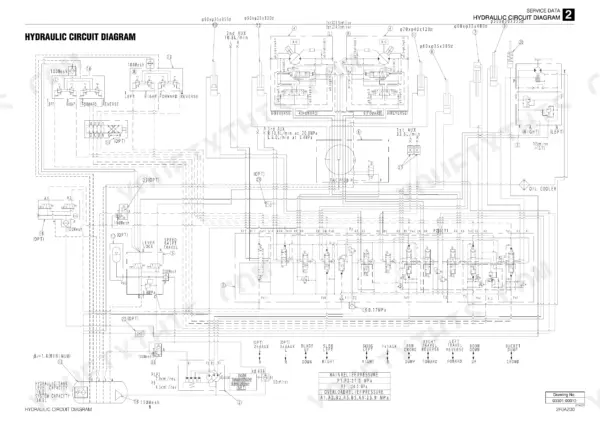
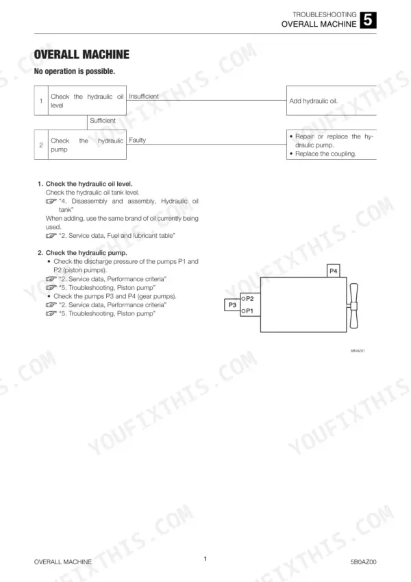
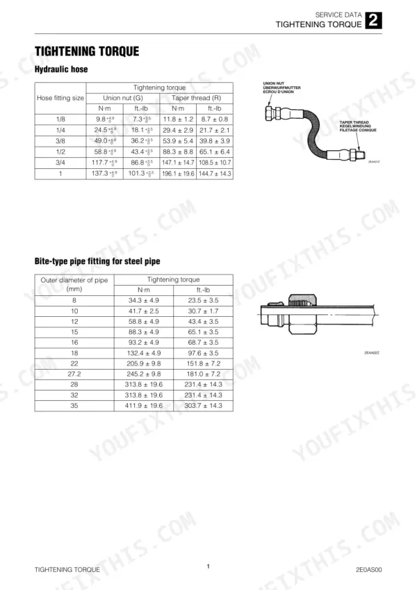
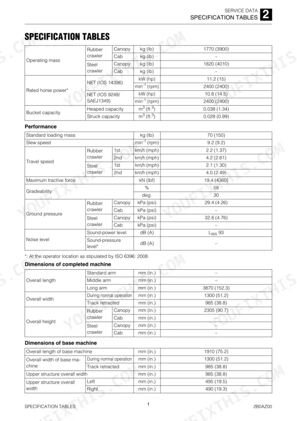
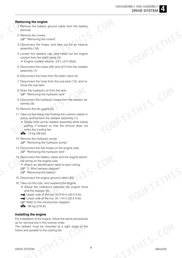
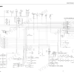
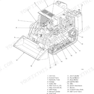
This 276-page Takeuchi TB216 Mini Excavator Workshop Manual (OEM #CC7E000) puts the full factory rebuild process for your machine in one place: engine, hydraulic system, travel system, slew equipment, and working equipment. Inside you get wiring diagrams for the electrical circuit, hydraulic schematics covering the piston pump, gear pump, and control valve, plus a disassembly and assembly section that walks you through the drive system, upper frame, and attachments step by step. A full troubleshooting section breaks down faults across traveling, boom, arm, bucket, and auxiliary hydraulics, so you're not chasing symptoms blind. Set pilot pressure to 3.43 MPa (497 PSI) and torque the hydraulic tank bolts to 47 N-m (34.7 ft.-lb), straight from the factory data. Stop guessing at lever lock and pilot valve specs because a forum thread gave you a rough number. This PDF is bookmarked and searchable, so you can jump straight to the spec you need instead of flipping through 276 pages.
What's Inside This Manual
| System | Pages | Key Topics |
|---|
| Introduction | 1-2 | Engine, Hydraulic System, Electrical Circuit Diagram, Travel System, Slew Equipment, Working Equipment |
| Safety | 3-12 | |
| Service Data | 13-59 | Dimensional Drawing, Specification Tables, Table of Masses, Lubricant and Fuel Chart, Performance Criteria, Tightening Torque, Hydraulic Circuit Diagram, Electrical Circuit Diagram |
| Function | 60-84 | Hydraulic Pump (Piston), Gear Pump, Control Valve, Pilot Valve (Control Lever), Solenoid Valve(3Rd Auxiliary Line Piping), Solenoid Valve (Lever Lock), Cylinders, Travel Motor |
| Drive System | 86-100 | Service Standards |
| Operating Device | 101-123 | Slew Equipment, Travel System, Upper Frame |
| Hydraulic Pump | 124-143 | Attachments, Hydraulic Tank |
| Control Valve | 144-156 | Right Travel Section, Left Travel Section, Swing Section, Boom Section, Slew Section, Arm Section, Bucket Section |
| Cylinders | 157-181 | Pilot Valve, Solenoid Valve (3RD Auxiliary Line Piping) |
| Travel Motor | 182-197 | Reduction Gears, Valves, Assembly, Inspection and Adjustments |
| Slew Motor | 198-210 | Brake Valve, Hydraulic Motor |
| Swivel Joint | 211-216 | Selector, Hub, Shaft, Flange, Thrust Ring |
| Troubleshooting | 217-259 | Overall Machine, Traveling, Boom, Arm, Bucket, Boom Swing, Dozer Blade, Auxiliary Hydraulics (1st) |
| Other | 260-276 | Monochrome LCD Cluster, Panel Display, LCD Specifications, Water Temperature Gauge, Fuel Gauge, Function/Warning Lamps, Normal Screen, Main Menu Screen |
Quick Reference Specifications
| Specification | Value | Page |
|---|
| Seals and cotter pins replacement | Be sure to replace all seals and cotter pins with new ones. | p. 11 |
| Pilot pressure | 3.4 MPa (493 PSI) | p. 29 |
| Locknut | 15.7 N·m (11.6 ft.-lb) | p. 31 |
| Lever control force | 28 N (6.31 lbf) | p. 119 |
| Hydraulic tank bolt torque | 47 N·m (34.7 ft.-lb) | p. 133 |
| Hydraulic tank oil plug torque | 8 N·m (5.9 ft.-lb.) | p. 153 |
| Seals replacement | Replace seals with new ones after each disassembly. | p. 137 |
| Sliding surface with the valve body | If there are abnormal scratches, wear, or seizure on the surface | p. 197 |
| Sliding surface with the check valve | If there are abnormal scratches, wear, or seizure on the surface | p. 197 |
| Operating Mass (Rubber crawler, Canopy) | 1770 kg | p. 18 |
| Rated Horse Power (NET IOS 14396) | 11.2 kW | p. 18 |
| Bucket Capacity (Heaped) | 0.038 m³ | p. 18 |