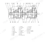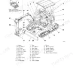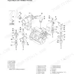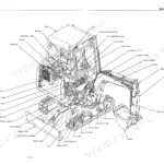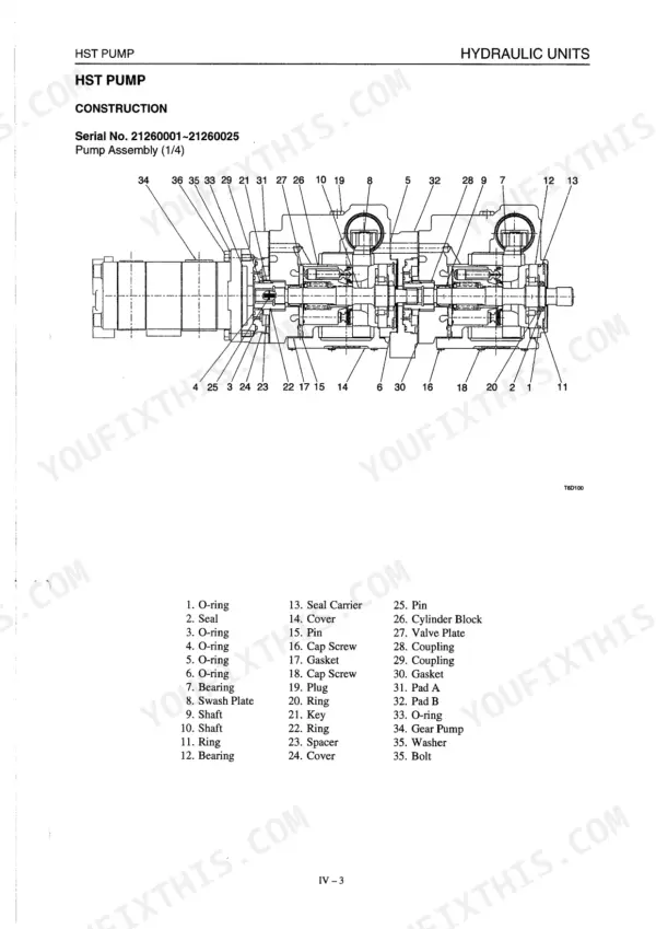
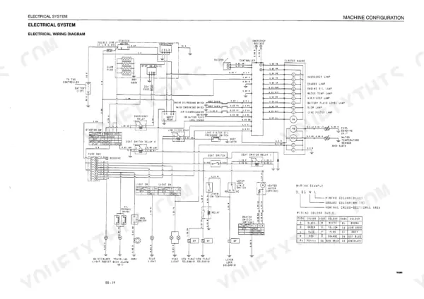
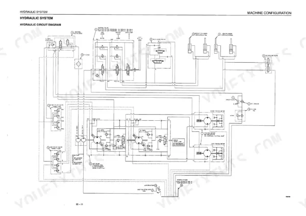
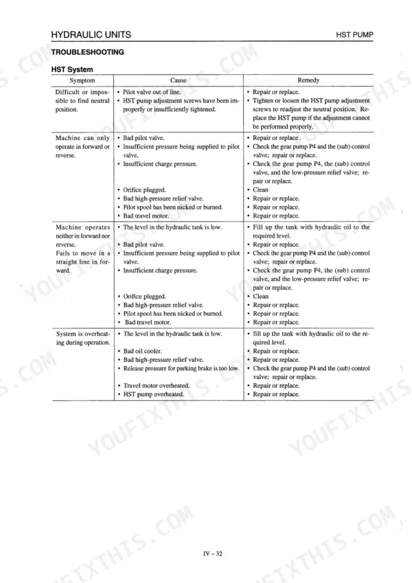
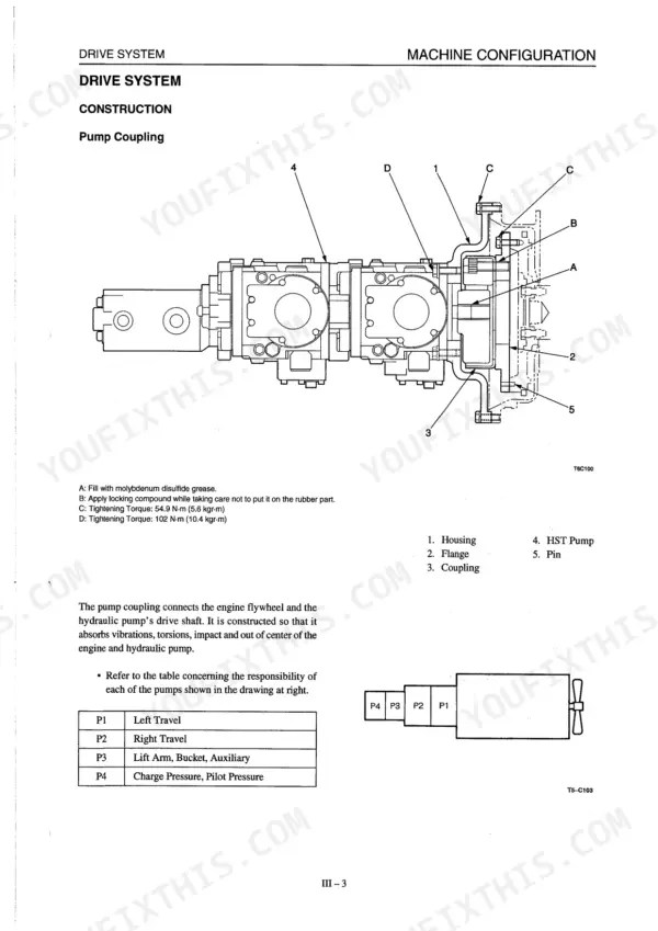
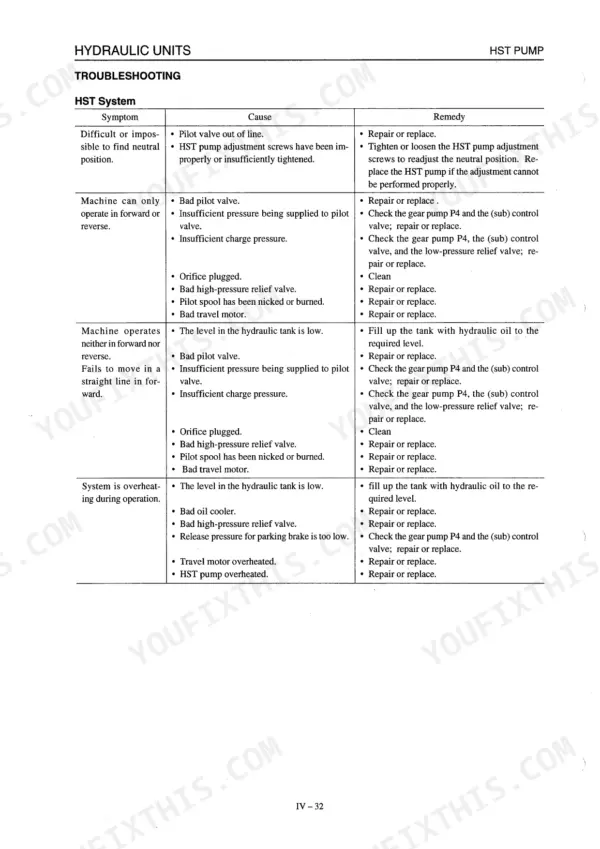
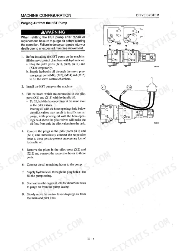
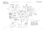
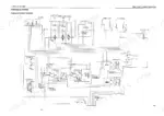
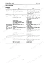
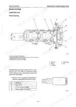
Across 114 pages, the Takeuchi TL126 shop manual PDF (OEM ID WT6E000) gives you one factory source for servicing this crawler loader. Wiring diagrams and hydraulic schematics trace the electrical wiring and the hydrostatic circuit, including how oil moves in neutral and forward travel. HST pump and travel motor chapters cover construction, disassembly and assembly, while the troubleshooting section works through insufficient power, lift arm or bucket failure, travel train faults and high temperature operation. Check control valve (sub) pressure against 2.9 ± 0.2 MPa (30 ± 2 kgf/cm²), and hold track roller shaft to bushing bore clearance within 0.100 to 0.275 mm. Your job might be a charge pressure or pilot pressure check, or measuring natural cylinder drop against the Standards for Judging Performance. Pay once and it stays yours. The bookmarked, text-searchable file belongs with this machine for as long as you run it.
What's Inside This Manual
| System | Pages | Key Topics |
|---|---|---|
| Specification Tables | 7-10 | Dimensions, Working Range, Performance, Cycle Time, Engine, HST Pump, Gear Pump, Control Valve |
| Weight Tables | 11 | Engine Assembly, Radiator Assembly, Oil Cooler, HST Pump, Hydraulic Tank Assembly, Fuel Tank Assembly, Control Valve, Pilot Valve |
| Fluid Capacities | 12 | Hydraulic Oil, Engine Oil, Travel Reduction Gear, Track Roller, Idler, Fuel Tank, Engine Cooling System |
| Recommended Lubricants | 13 | Hydraulic Oil, Reduction Gears, Grease Fittings |
| Servicing Standards | 14-15 | Tread Outer Diameter, Width of Tread, Shaft and Bushing Bore Diameter Clearance, Roller and Bushing Outer Diameter Interference, Shaft End Play |
| Standards for Judging Performance | 16 | Hydraulic Oil Pressure, Travel Speed, Travel Curve, Natural Travel Drop, Cylinder Speed, Natural Cylinder Drop, Lever Operating Force, Lever Play |
| Methods for Inspecting Performance | 17-18 | Hydraulic Oil Pressure, Travel Relief Valve, Charge Pressure, Pilot Pressure |
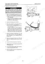
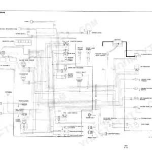
| Machine Configuration | 19-36 | Drive System, Travel System, Frame, Canopy, Control System, Electrical Wiring Diagram |
| Hydraulic Units | 37-92 | HST Pump Construction, HST Pump Disassembly and Assembly, Control Valve (Sub) Construction, Travel Motor Construction, Travel Motor Disassembly and Assembly |
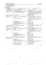
| Troubleshooting | 93-110 | Trouble Diagnosis Procedures, Complete Failure of All Systems, Insufficient Power, Lift Arm or Bucket Failure, Travel Train Fault, High Temperature Operation |
| Hydraulic Circuitry | 111-114 | Hydrostatic Circuit Description, Neutral Circuit Operation, Forward Travel Circuit Operation |
Quick Reference Specifications
| Specification | Value | Page |
|---|---|---|
| Track Roller (08801-30000) Shaft and Bushing Bore Diameter Clearance Standard | 0.100-0.275 mm | p. 14 |
| Track Roller (08801-30000) Roller and Bushing Outer Diameter Interference Standard | 0.095-0.16 mm | p. 14 |
| Forced Release of the Parking Brakes cap screw | M10 X 30 mm P1.5 | p. 78 |
| Thrust plate clearance (Value A) | 0.3 to 0.7 mm | p. 89 |
| Control valve (sub) pressure | 2.9 ± 0.2 MPa (30 ± 2 kgf/cm²) | p. 99 |
| Weight in Transport Condition | 3010 kg | p. 7 |
| Travel Speed | 0 ~ 8.5 km/h | p. 7 |
| Hydraulic Oil Tank Level Capacity | 50 l | p. 12 |
| Engine Oil Capacity (Upper Limit / Lower Limit) | 6.3/4.6 l | p. 12 |
| Travel Reduction Gear Oil Capacity | 1.3 l | p. 12 |
| Fuel Tank Capacity | 59 l | p. 12 |
| Engine Cooling System Capacity | 12.5 l | p. 12 |