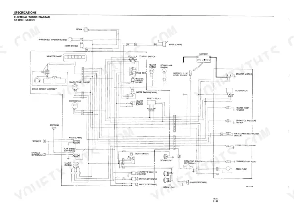
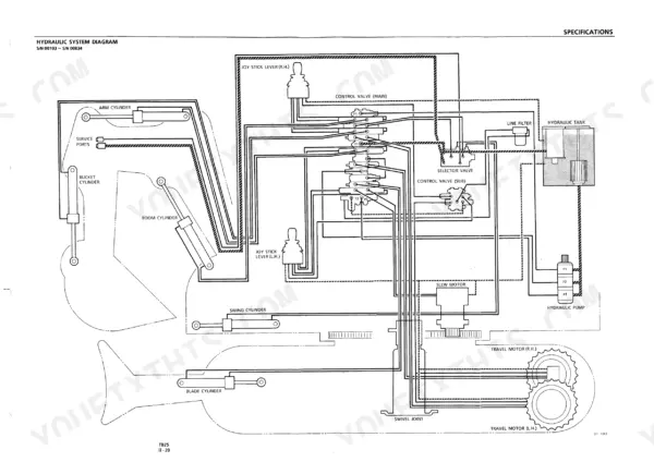
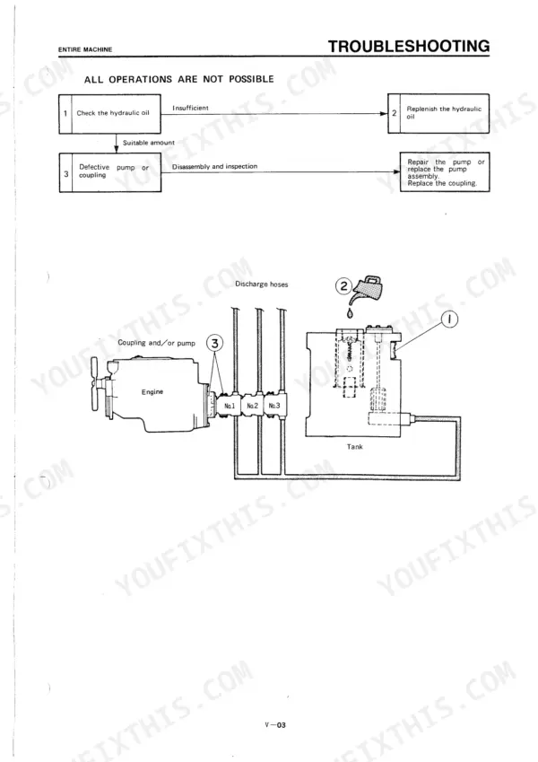
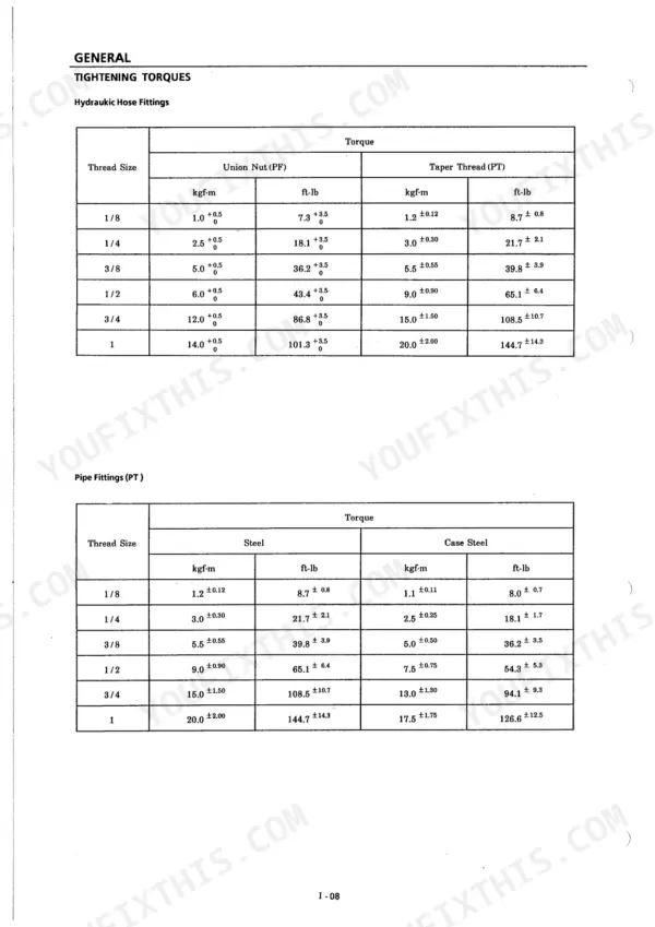
Across 258 pages, the Takeuchi TB25 shop manual PDF covers the TB25 compact excavator from teardown through final performance checks. Hydraulic system diagrams lay out the circuits from pump and control valve to the travel and slew motors, and electrical wiring diagrams map the machine's circuits. Troubleshooting is sorted by function: entire machine, travelling, slewing, boom, arm, bucket, boom swing and dozer blade. Torque tables cover hose fittings, pipe fittings and 10.9 bolts. Fill to a 72 l total hydraulic system capacity, and on serials 00103 to 00834 check the P1 and P2 main relief valves at 190 kgf/cm² at 22 l/min. If your job is pulling a hydraulic unit and its piping, with the seal handling that goes with it. Section bookmarks and a searchable text layer take you straight there, and the fittings go back on at the tightening torques the book prints.
What's Inside This Manual
| System | Pages | Key Topics |
|---|
| General Cautions | 9 | Safety Guidelines |
| Cautions During Disassembly and Reassembly | 10 | Disassembly Procedures |
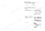
| Cautions During Removal and Installation of the Hydraulic Units | 11 | Hydraulic Unit Handling |
| Cautions During Removal and Installation of Piping | 12 | Hydraulic Hose Installation |
| Handling of Seals | 13 | O-Ring Handling |
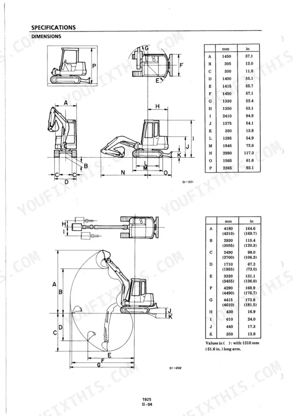
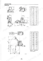
| Tightening Torques and General Specifications | 14-24 | Hydraulic Hose Fittings, Pipe Fittings, ISO Strength Category 10.9 Bolts, Machine Dimensions, Lifting Capacities |
| Hydraulic Unit Specifications and Fluid Capacities | 25-26 | Main Relief Valve Settings, Travel Motor Displacement, Slew Motor Displacement, Hydraulic Pump Displacement, Fluid Capacities |
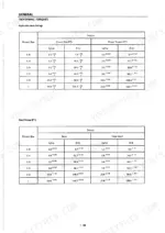
| Performance Check Judgment Standards | 27-35 | Travel Speed, Travel Curve, Slewing Time, Cylinder Natural Fall, Swing Cylinder Natural Fall |
| General Check Judgment Standards | 36-44 | Lever Operating Force, Slew Bearing Backlash, Crawler Belt Tension, Pin and Bushing Wear, Bucket Tooth Wear |
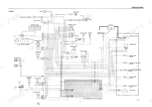
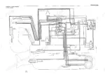
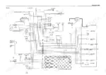
| Lubricants and Hydraulic/Electrical Diagrams | 45-52 | Recommended Lubricants, Hydraulic System Diagrams, Electrical Wiring Diagrams |
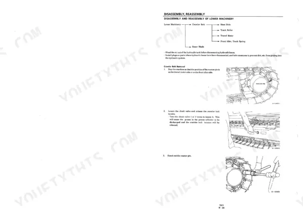
| Disassembly and Reassembly Procedures | 53-108 | Lower Machinery, Hoe Attachment, Upper Machinery, Swivel Joint, Slew Bearing |
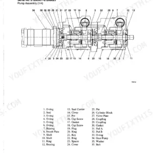
| Hydraulic Units Structure and Operation | 109-206 | Hydraulic Tank, Hydraulic Pump, Relief Valve, Control Valve, Travel Motor, Slew Motor, Swivel Joint |
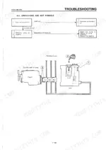
| Troubleshooting Procedures | 207-258 | Entire Machine, Travelling, Slewing, Boom, Arm, Bucket, Boom Swing, Dozer Blade |
Quick Reference Specifications
| Specification | Value | Page |
|---|
| Main Relief Valve Settings (S/N 00103 ~ 00834) P1, P2 | 190 kgf/cm² @ 22 l/min | p. 25 |
| Main Relief Valve Settings (S/N 00103 ~ 00834) P3 | 150 kgf/cm² @ 22 l/min | p. 25 |
| Hydraulic Oil Tank Capacity | 59 l | p. 26 |
| Hydraulic Oil Total System Capacity | 72 l | p. 26 |
| Steel Crawler Belt Tension | 125 ~ 145 mm | p. 38 |
| Rubber Crawler Belt Tension | 105 ~ 110 mm | p. 38 |
| Grease amount for spline | 50 cc | p. 90 |
| Main Relief Valve Setting (P1, P2) (S/N 00103-00834) | 190 kgf/cm² @ 22 l/min | p. 25 |
| Main Relief Valve Setting (P3) (S/N 00103-00834) | 150 kgf/cm² @ 22 l/min | p. 25 |
| Fuel Tank Capacity | 40 l | p. 26 |
| Cooling System Capacity | 5.5 l | p. 26 |
| Travel Motor Reduction Gear Capacity | 600 cc | p. 26 |