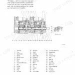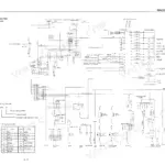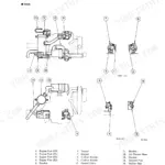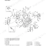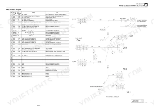
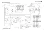
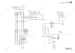
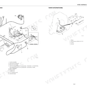
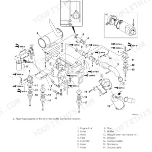
Written for the TL220 track loader and issued under OEM ID CU0E003, this 282-page Takeuchi TL220 service manual PDF runs from safety precautions through engine data. Hydraulic and electric circuit diagrams show how the control valve's lift arm, bucket and auxiliary sections connect, while troubleshooting charts sort faults by symptom: a lift arm that drops once when the lever is pulled slowly, a machine that veers to one side, 2nd speed travel that will not engage. Teardown chapters follow the HST pump, travel motor and cylinders. Check hydraulic pump set pressure against 3.3 MPa, then torque the HST pump drain plug to 95 to 135 N·m. If proportional control on your auxiliary hydraulics has quit, the circuit diagrams trace that circuit through the proportional control solenoid valve. Search the text or jump by bookmark to the HST pump section, and you can finish the rebuild within the stated idle run torque of 8.5 N·m or less.
What's Inside This Takeuchi TL220 Manual
| System | Pages | Key Topics |
|---|---|---|
| Safety | 3-12 | Safety Alert Symbol, Safety Precautions, Cautions When Working |
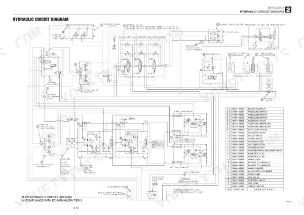
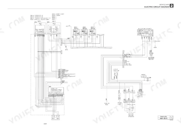
| Service Data | 13-55 | Dimensional Drawing, Specifications Tables, Lubricant and Fuel Chart, Performance Criteria, Tightening Torque, Hydraulic Circuit Diagram, Electric Circuit Diagram |
| Function | 56-97 | HST Pump, Gear Pump, Control Valve, Sub Valve, Self-Level Valve, Pilot Valve, Proportional Control Solenoid Valve, Cylinders, Charge Relief Valve, Flushing Valve, Load Check Valve, Main Relief Valve, Port Relief Valve, Cushion Mechanism, Reduction Gears, Heater System Operation |
| Service Standards | 99-100 | Track Roller a, Track Roller B, Drive Sprocket, Idler, Pin and Bushing Clearance |
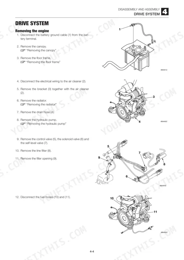
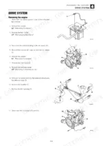
| Drive System | 101-107 | Engine Removal, Engine Installation, Radiator Removal, Radiator Installation, Hydraulic Pump Removal, Hydraulic Pump Installation |
| Travel System | 108-110 | Crawler Belt Removal, Crawler Belt Installation, Track Roller Removal, Track Roller Installation, Idler Removal, Travel Motor Removal |
| Frame | 111-115 | Canopy Tilting, Lift Arm Stopper, Floor Frame Removal, Cover Removal, Canopy Removal, Cab Removal |
| Control System | 116-117 | Hydraulic Pilot Unit, Lever Stand Removal, Lever Stand Installation |
| Attachments | 118-124 | Quick-Hitch Removal, Quick-Hitch Installation, Lift Arm Removal, Lift Arm Installation, Bucket Stopper Adjustment, Arm Stopper Adjustment |
| Hydraulic Tank | 125-126 | Hydraulic Tank Removal, Hydraulic Tank Installation, Hydraulic Oil Filling, Air Bleeding |
| HST Pump | 127-150 | Pump Assembly Construction, Pump Disassembly, Pump Assembly, Rotational Torque Adjustment, Neutral Adjustment, Displacement Limiter Adjustment |
| Gear Pump | 151-155 | Disassembly, Inspection and Adjustment, Test Operation, Measuring the Discharge Volume |
| Control Valve | 156-161 | Lift Arm Section, Bucket Section, Auxiliary Section, Main Relief Valve, Port Relief Valve |
| Sub Valve | 162-166 | Disassembly, Inspection and Adjustment, Construction, Solenoid Valve a, Coil Assembly |
| Self-Level Valve | 167-170 | Disassembly, Inspection and Adjustment, Construction, Poppet, Needle, Checking the Parts |
| Pilot Valve | 171-177 | Special Tools, Disassembly, Assembly, Inspection and Adjustment |
| Proportional Control Solenoid Valve | 178-179 | Disassembly, Inspection and Adjustment, Construction, Spool, Sleeve, Coil Assembly |
| Cylinders | 180-193 | Disassembly, Assembly, Inspection and Adjustment, Inspection After Assembly |
| Travel Motor | 194-213 | Hydraulic Motor, 2-Speed Mechanism, Parking Brake, Flushing Valve, Reduction Gears, Special Tools |
| Air Conditioner | 214-217 | Compressor Assembly, Condenser Assembly, Air Conditioner Unit, AC Component |
| Troubleshooting | 218-281 | Overall Machine (No Operation Is Possible., All Systems Working, But Insufficient Power., Lift Arm and Bucket Fail to Move or Are Too Slow.) |
| Engine | 282 | Model, Mounted Engine, 4TNV84T |
Quick Reference Specifications
| Specification | Value | Page |
|---|---|---|
| Pilot valve (right) pressure | 2.9 MPa | p. 222 |
| Hydraulic pump displacement | 20.4 + 11.6 cm3/rev | p. 17 |
| Hydraulic pump set pressure | 3.3 MPa | p. 17 |
| Drain plug torque | 95 to 135 N·m | p. 144 |
| Idle run torque | 8.5 N·m or less | p. 144 |
| Thrust plate thickness X | 0.2 to 0.4 mm thinner than the thickness of A plus B | p. 211 |
| Thrust plate bolt torque | 25 N·m | p. 211 |
| Center disc and friction disc wear limit | 13.5 mm or less | p. 213 |
| Pilot valve (left) pressure | 2.2 MPa | p. 222 |
| Engine oil pan capacity (Upper limit) | 7.4 L | p. 18 |
| Hydraulic oil tank capacity | 29 L | p. 18 |
| Engine cooling system capacity | 11.0 L | p. 18 |
Takeuchi TL220 Common Problems This Manual Covers
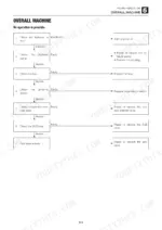
Takeuchi TL220 lift arms, bucket and travel all dead with engine running, no hydraulic operation possible
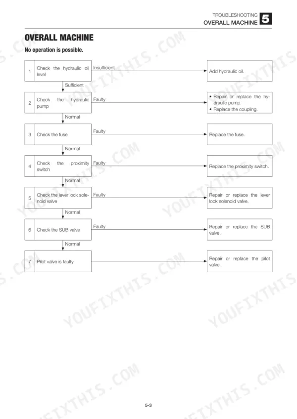
Check hydraulic oil level first, then confirm pumps P3 and P4 discharge oil with the hose off (a faulty coupling stops them). Test the fuse, the proximity switch voltage at the lever lock solenoid, and solenoid vibration. Release hydraulic pressure before disconnecting any line (page 9), then fit a gauge to the SUB valve: pilot pressure should read 2.9 MPa right and 2.2 MPa left, per page 222.
Manual Section: Overall machine p. 220Hydraulic pump noisy, all systems working but insufficient power, frothing in the hydraulic tank
Check oil level, then apply grease or oil on suspect suction joints; if the noise changes, air is getting in, so replace the seal tape, O-ring and hose. Inspect the suction filter and line filter element for clogging, releasing system pressure before opening the case (page 9). If pump wear left metal in the oil, replace line and spin filter elements and flush using oil of NAS grade up to 9, per page 224.
Manual Section: Overall machine p. 223Lift arm and bucket cylinders both fail to move or operate too slowly
Check hydraulic pump P3 by disconnecting its discharge hose and confirming oil flows with the engine running; release hydraulic pressure before breaking the line (page 9). Then measure main relief valve pressure. If it reads below spec, tighten the set screw gradually; if pressure does not rise after 1/4 turn, repair or replace the relief valve. A good pump and relief valve point to the pilot valve, per page 225.
Manual Section: Overall machine p. 225One track slows down and the machine veers to one side during straight travel
Verify the veering value with the straight-ahead traveling test first; within spec, the machine is normal. Clear foreign matter from the crawler belt and set crawler tension to 25 to 50 mm (page 20), keeping your body clear of the grease discharge valve, which can fly off (page 9). Check pilot secondary pressure for 0 to 2.2 MPa (page 227), then swap a high-pressure relief valve; if veering switches sides, that valve is faulty.
Manual Section: Traveling p. 228Travel system operating temperature running too high, travel motor or HST pump generating heat
Stop the engine and let the machine cool before touching anything, and never remove the radiator cap hot (page 8). Check hydraulic oil level, the suction filter and dirt in the oil cooler and radiator fins, cleaning both. Release hydraulic pressure (page 9), fit a gauge at the SUB valve and confirm 2.9 MPa parking brake release pressure per page 230; low pressure points to the SUB valve, filter or pump P4.
Manual Section: Traveling p. 229Arm cylinder slow with insufficient power even though the pilot valve and spool check normal
Test the port relief valve by swapping in the bucket's port relief valve, then check the arm float solenoid valve for foreign matter on the seat or a sticking poppet. Release hydraulic pressure before opening lines (page 9). For the leak test, lower the bucket about 10° forward onto its tip, plug the rod side hose, tilt back and lift; oil from the rod piping while lowering means control valve leakage, per page 236.
Manual Section: Lift arm p. 235Frequently Asked Questions
Why is the Takeuchi TL220 not moving?
If the machine is not moving, check the hydraulic oil level, the hydraulic pump, the fuse, the proximity switch, the lever lock solenoid valve, the SUB valve, or the pilot valve. For example, if the fuse is faulty, replace it. If the hydraulic pump is faulty, repair or replace it or the coupling. Refer to page 220 for the troubleshooting chart. p. 220
Why are the lift arms or bucket slow on a Takeuchi TL220?
If the lift arm or bucket fails to move or is too slow, check the hydraulic pump P3, the main relief valve, or the pilot valve. If the hydraulic pump P3 is faulty, repair or replace it. If the main relief valve is faulty, repair or replace it. Refer to page 225 for the troubleshooting chart. p. 225
How do I check the hydraulic pressure for the travel system?
To check the travel hydraulic pressure, ensure the engine is at maximum RPM and the hydraulic oil temperature is between 50 and 60°C. Install a pressure gauge on the pressure detection port (P1 for left travel, P2 for right travel) and measure the relief pressure. The standard value is 26.5 MPa. p. 22
What is the tightening torque for the hydraulic hose union nut with a 1/2 inch fitting size on the Takeuchi TL220?
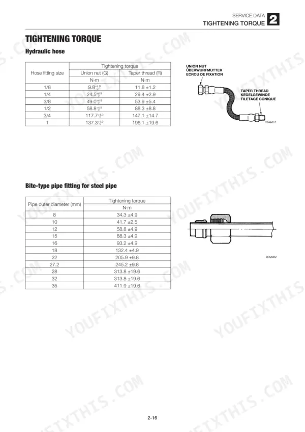
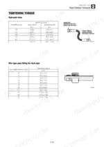
The tightening torque for a 1/2 inch hydraulic hose union nut (G) is 58.8 +4.9 N·m. For the taper thread (R) of the same size, the torque is 88.3 ±8.8 N·m. p. 28
What is the engine oil capacity for the TL220?
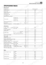
The engine oil pan capacity for the TL220 is 7.4 L for the upper limit and 4.0 L for the lower limit. The oil should be changed every 250 hours after the first 50 hours. p. 18
How quickly can I access this Takeuchi TL220 manual after buying?
A single searchable PDF file of 282 pages, downloadable right after payment. Nothing ships, nothing waits in the mail.
Is this Takeuchi TL220 Service Manual printable?
Yes. Print a single page or a chapter for your own shop use, on letter or A4.