| Safety | 3-12 | Safety Alert Symbol, Safety Label, Safety Precautions, Cautions When Working, Handling of Seals |
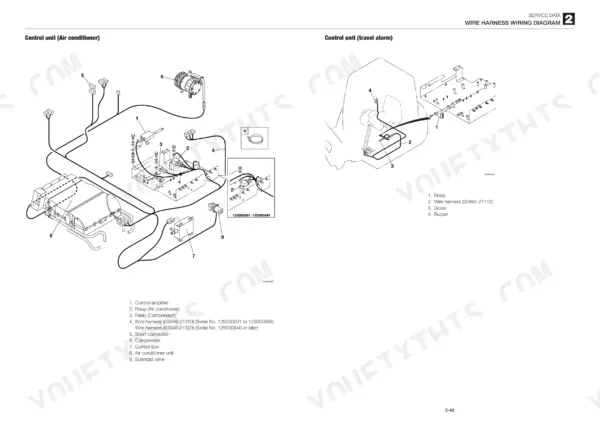
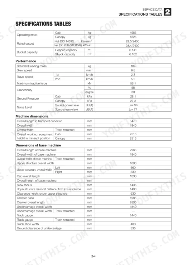
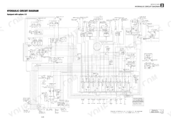
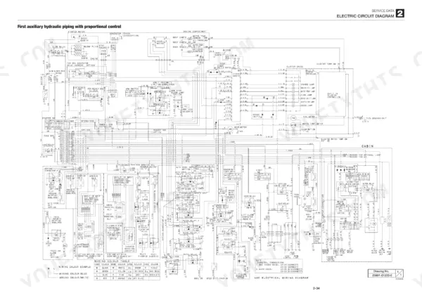
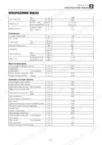
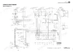
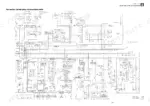
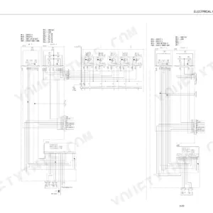
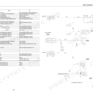
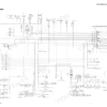
| Service Data | 13-81 | Dimensional Drawing, Specifications Tables, Lubricant and Fuel Chart, Performance Criteria, Tightening Torque, Hydraulic Circuit Diagram, Electric Circuit Diagram |
| Function | 82-105 | Piston Pump, Gear Pump, Control Valve, Pilot Valve, Proportional Control Solenoid Valve, Emergency Shut-Off Valve, Cylinders, Travel Motor |
| Service Standards | 107-109 | Carrier Roller, Track Roller, Drive Sprocket, Idler, Clearance for Pin and Bushing |
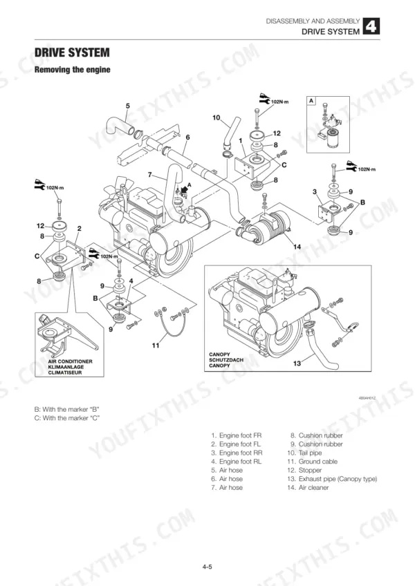
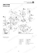
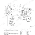
| Drive System | 110-118 | Removing the Engine, Removing the Radiator and Oil Cooler, Removing the Hydraulic Pump, Removing the Fuel Tank, Adjusting the Throttle Lever |
| Travel System | 119-123 | Removing the Crawler Belt, Installing the Crawler Belt, Removing the Steel Crawler, Installing the Steel Crawler, Removing the Carrier Roller, Removing the Track Roller |
| Slew System | 124-126 | Removing the Slew Motor, Removing the Slew Bearing, Removing the Swivel Joint |
| Upper Frame | 127-132 | Removing the Upper Frame, Removing the Covers, Removing the Cab |
| Control System | 133-143 | Removing the Lever Stand, Adjusting the Control Cable, Hydraulic Pilot Unit, Blade Lever, Lever Stand, Control Box R, Control Box L |
| Attachments | 144-149 | Removing the Attachments, Removing the Bucket, Removing the Link, Removing the Arm, Removing the Boom, Removing the Swing Bracket, Removing the Dozer Blade |
| Hydraulic Tank | 150-154 | Tank, Pipe Assembly, Suction Filter, Return Filter, Sight Gauge, Air Breather |
| Hydraulic Pump | 155-178 | Shaft, Swash Plate, Cylinder Block, Gear Pump, Housing, Solenoid Valve |
| Control Valve | 179-190 | Tie Rod, Bucket Section, Boom Section, Right Travel Section, Inlet Housing, Arm Section |
| Pilot Valve | 191-225 | Casing, Plate, Spool, Push Rod, Spring Seat, Adjusting Nut, Proportional Control Solenoid Valve, Pilot Valve (Auxiliary), Pilot Valve (Travel), Proportional Control Solenoid, Case, Cover, Plug, Seal, Grease Cup, Damping Spring |
| Solenoid Valve (1-Section) | 226-228 | Plug, Solenoid Valve, Spring, Spool, Body |
| Solenoid Valve (2-Section) | 229-231 | Solenoid Coil, Push Rod, Cap Screw, Checking the Parts, Assembly |
| Cylinders | 232-248 | Boom Cylinder, Arm Cylinder, Bucket Cylinder, Dozer Blade Cylinder, Swing Cylinder, Piston Rod Assembly, Leak Test, Bleeding Air From the Hydraulic Cylinder, Assembly |
| Travel Motor | 249-263 | Hydraulic Motor, Counterbalance Valve, 2-Speed Mechanism, Reduction Gears, Parking Brake, Inspection, Adjustment |
| Slew Motor | 264-282 | Hydraulic Motor, Relief Valve, Make-Up Valve, Anti-Rebound Valve, Parking Brake, Timer Valve, Reduction Gears, Brake Valve |
| Swivel Joint | 283-287 | Thrust Ring, Slipper Seal, Dust Seal, Snap Ring, Backup Ring, Use Limit for Parts, Inspection After Assembly, Assembly |
| Air Conditioner | 288-291 | Removing Upper Case, Replacing Blower Motor, Replacing Evaporator, Replacing Expansion Valve, Replacing Heater Core, Maintenance, Troubleshooting |
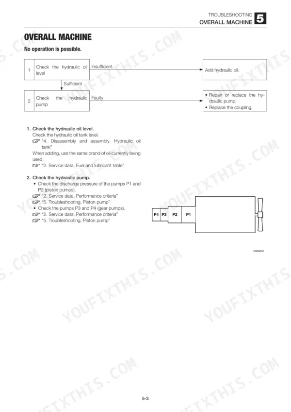
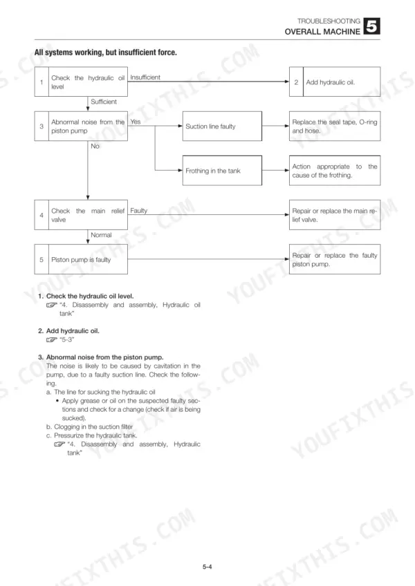
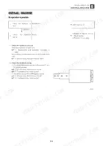
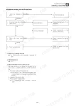
| Troubleshooting | 292-351 | Overall Machine, Traveling, Boom Swing, Dozer Blade, Auxiliary Hydraulics, Piston Pump, Gear Pump, Control Valve, Proportional Control Solenoid Valve, Travel Motor, Slew Motor, Air Conditioner, Overall Machine (No Operation Is Possible., Boom, Bucket, Slew and Arm Fail to Move or Are Too Slow.) |
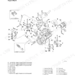
| Engine | 352 | Mounted Engine |