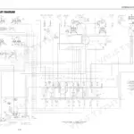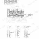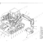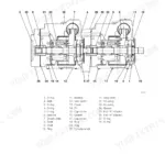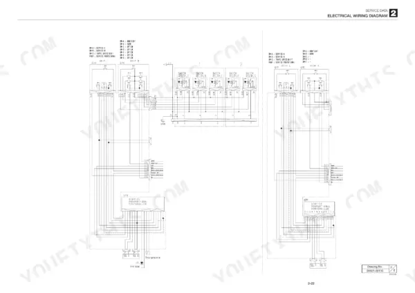
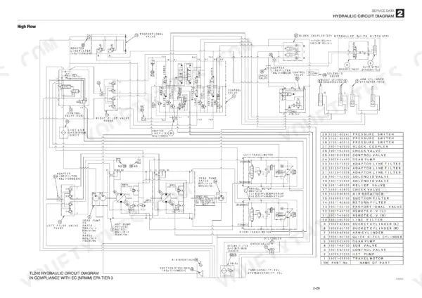
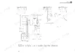
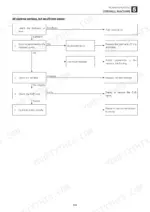
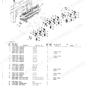
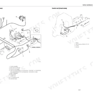
Written for the Takeuchi TL240 track loader, publication CU2E003 runs 344 pages, and this Takeuchi TL240 service manual PDF reproduces all of it. Its Service Data chapter carries the hydraulic circuit diagram, electrical wiring and wire harness diagrams, specification tables and tightening torque values. Later chapters strip the HST pump, control valves, cylinders and travel motor down to the charge pressure relief valve and 2-speed mechanism, and troubleshooting charts cover faults such as a lift arm that drops once when the control lever is pulled slowly. Check the hydraulic drive system set pressure against 34.5 MPa, and measure sprocket dimension A: 410 mm standard, 402 mm allowable. Chasing an electrical circuit is where the wiring and harness diagrams earn their place, showing the connections along your route. The bookmarked, text-searchable file goes wherever your TL240 works.
What's Inside This Takeuchi TL240 Manual
| System | Pages | Key Topics |
|---|---|---|
| Safety | 3-12 | Safety Alert Symbol, Safety Precautions, Cautions When Working |
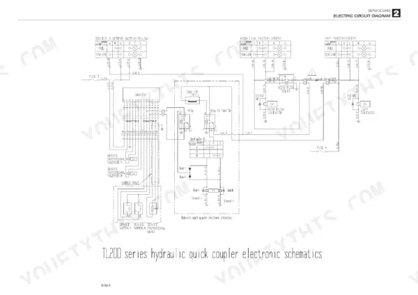
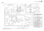
| Service Data | 13-71 | Dimensional Drawing, Specifications Tables, Lubricant and Fuel Chart, Performance Criteria, Tightening Torque, Hydraulic Circuit Diagram, Electrical Wiring Diagram |
| Function | 72-121 | Charge Relief Valve, Main Relief Valve, Load Check Valve, Port Relief Valve, Cushion Mechanism, Air Conditioner System |
| Service Standards | 123-124 | Track Roller, Sprocket, Idler, Pin and Bushing Clearance |
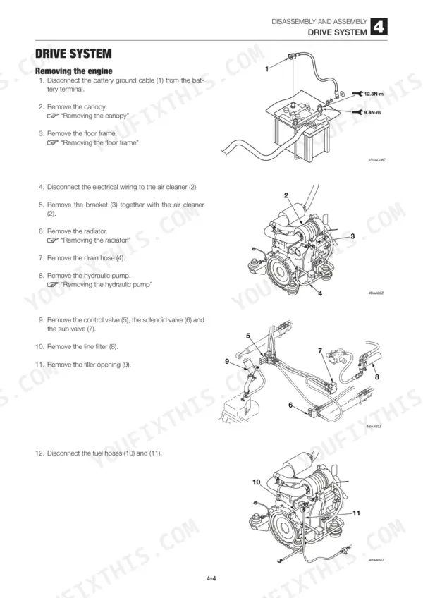
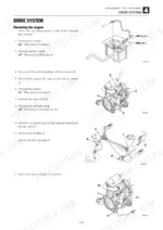
| Drive System | 125-131 | Engine, Radiator, Hydraulic Pump, Fuel Tank, Throttle Lever |
| Travel System | 132-134 | Crawler Belt, Track Roller, Idler, Track Adjuster, Travel Motor |
| Frame | 135-139 | Canopy, Floor Frame, Cover, Lift Arm Stopper |
| Control System | 140-141 | Hydraulic Pilot Unit, Lever Stands |
| Attachments | 142-148 | Quick-Hitch, Lift Arm, Bucket Stopper, Arm Stopper |
| Hydraulic Tank | 149-150 | Hydraulic Oil, Sight Gauge, Suction Pipe |
| HST Pump | 151-201 | Orifice, Control Cover, Front Shaft, Rear Shaft, Charge Pressure Relief Valve, Servo Piston |
| Gear Pump | 202-206 | Drive Gear, Driven Gear, Adapter Plate, Bushing, Construction, Disassembly, Inspection, Adjustment, Test Operation |
| Gear Pump (High Flow) | 207-211 | Rear Cover, Oil Seal, Snap Ring, Construction, Disassembly, Inspection, Adjustment, Test Operation |
| Control Valve | 212-217 | Load Check Valve (B), Flow Ratio Adjuster Valve, Construction, Disassembly, Assembly, Main Relief Valve, Port Relief Valve, Spool |
| Control Valve (High Flow) | 218-221 | Inlet Housing, Tie Rod, Solenoid Coil, Construction, Disassembly, Inspection, Adjustment, Relief Valve Pressure |
| Sub Valve | 222-226 | Solenoid a, Solenoid B, Poppet, Piston, Construction, Disassembly, Inspection, Adjustment |
| Pilot Valve | 227-233 | Push Rod, Cam, Spring Seat, Adjusting Nut, Construction, Special Tools, Disassembly, Assembly, Inspection, Adjustment |
| Proportional Control Solenoid Valve | 234-235 | Proportional Control Solenoid, Coil Assembly, Construction, Disassembly, Inspection, Adjustment |
| Cylinders | 236-249 | Arm Cylinder, Bucket Cylinder, Piston Rod Assembly, Cushion Seal, Construction, Special Tools, Disassembly, Assembly, Inspection, Leak Test |
| Travel Motor | 250-271 | Hydraulic Motor, 2-Speed Mechanism, Parking Brake, Flushing Valve, Reduction Gears |
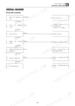
| Troubleshooting | 272-344 | Overall Machine (No Operation Is Possible., All Systems Working, But Insufficient Power., Lift Arm and Bucket Fail to Move or Are Too Slow.) |
Quick Reference Specifications
| Specification | Value | Page |
|---|---|---|
| Travel motor displacement | 25.7/41.0 cm3/rev | p. 16 |
| Hydraulic drive system set pressure | 34.5 MPa | p. 16 |
| Sproket Standard dimension A | 410 mm | p. 123 |
| Sproket Allowable value A | 402 mm | p. 123 |
| Arm cylinder & frame Standard clearance | 0.07 to 0.20 mm | p. 124 |
| Arm cylinder & lift arm Standard clearance | 0.07 to 0.20 mm | p. 124 |
| Crawler belt weight | 260 kg | p. 132 |
| Hydraulic tank capacity | 49 L | p. 149 |
| Hydraulic tank weight | 52 kg | p. 149 |
| Pilot valve (right) pressure | 3.2 MPa | p. 276 |
| Pilot valve (left) pressure | 2.1 MPa | p. 276 |
| Engine Oil Pan Capacity | 10.2 L | p. 18 |
Takeuchi TL240 Common Problems This Manual Covers
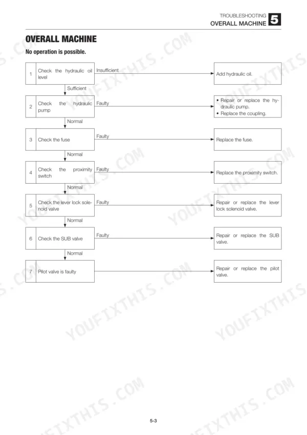
Takeuchi TL240 lift arms, bucket and travel all dead with no hydraulic operation possible
Check the hydraulic oil level first, then the fuse in the lever lock solenoid valve circuit. Move the safety bar to the driving position and test for voltage at the lever lock solenoid to prove the proximity switch (page 275). Release hydraulic system pressure before disconnecting the SUB valve to pilot valve hose (page 9), then gauge pilot pressure: 3.2 MPa right, 2.1 MPa left (page 276).
Manual Section: Overall machine p. 274Hydraulic pump noisy and all functions working but weak with insufficient power
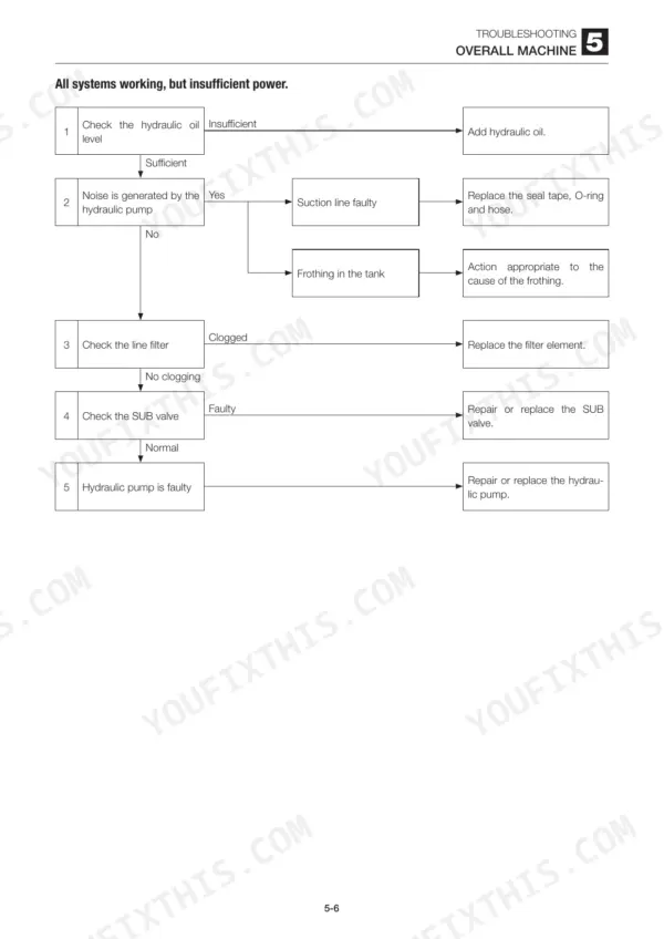
Check the hydraulic oil level, then hunt the suction line for air: smear grease or oil on suspect sections and watch for a change (page 278). Inspect the suction filter. Release hydraulic pressure before removing the line filter case (page 9), then check the element for clogging. If the pump is worn and shedding metal, replace the line and spin filter elements, replace or flush the oil, and clean the tank and suction strainer.
Manual Section: Overall machine p. 277Right or left travel speed decelerates and the machine veers to one side
Run the straight-ahead traveling test first; within spec means the machine is normal. Check crawler belt tension against 25 to 50 mm (page 20) and clear foreign matter from the belt, keeping your face and body away from the grease discharge valve while adjusting (page 9). Then check the pilot valve and HST pump discharge pressure, and swap a high-pressure relief valve: if veering moves to the opposite side, that valve is faulty.
Manual Section: Traveling p. 282Takeuchi TL240 travel system operating temperature climbs too high
Stop the engine and let the machine cool before inspecting (page 8). Check the hydraulic oil level, the suction filter, and the oil cooler and radiator fins for packed dirt; clean them. Release hydraulic pressure (page 9), then fit a gauge at the SUB valve travel motor port: parking brake release pressure should read 3.2 MPa (page 284). If low, check the SUB valve, filter and hydraulic pump P4.
Manual Section: Traveling p. 2832nd speed travel will not engage when the speed switch is pressed
Check hydraulic pump P4 and clean the inline filter if it is clogged, then measure pilot relief valve pressure following page 285. Test the 2nd speed switch for continuity with a tester. With the starter switch on, rest a finger on the 2nd speed solenoid end and turn the switch on; no vibration means a bad solenoid valve. Finally check the 2nd speed control valve spool for sticking or foreign matter (page 286).
Manual Section: Traveling p. 285Lift arm cylinder slow or weak with insufficient power on the lift circuit
Check arm cylinder speed against spec. Release hydraulic pressure (page 9), disconnect the pilot valve to arm block hose at the control valve and fit a gauge to it: expect 0 to 3.2 MPa across lever travel (page 287). Swap in the bucket port relief valve to test the arm side, check the arm float solenoid valve for foreign matter or a sticking poppet, then leak test the arm cylinder with the bucket lowered (page 290).
Manual Section: Lift arm p. 289Frequently Asked Questions
Why is the TL240 low on hydraulic power or slow to lift?
If the lift arm and bucket fail to move or are too slow, check the hydraulic pump P3. If the pump is faulty, it must be repaired or replaced. You should also measure the relief pressure of the main relief valve; if it is below the specification of 20.6 MPa, adjust it by tightening the set screw. p. 279
What is the engine oil pan capacity for the TL240?
The engine oil pan capacity for the TL240 is 10.2 L. The oil should be changed every 250 hours after the first 50 hours of operation. p. 18
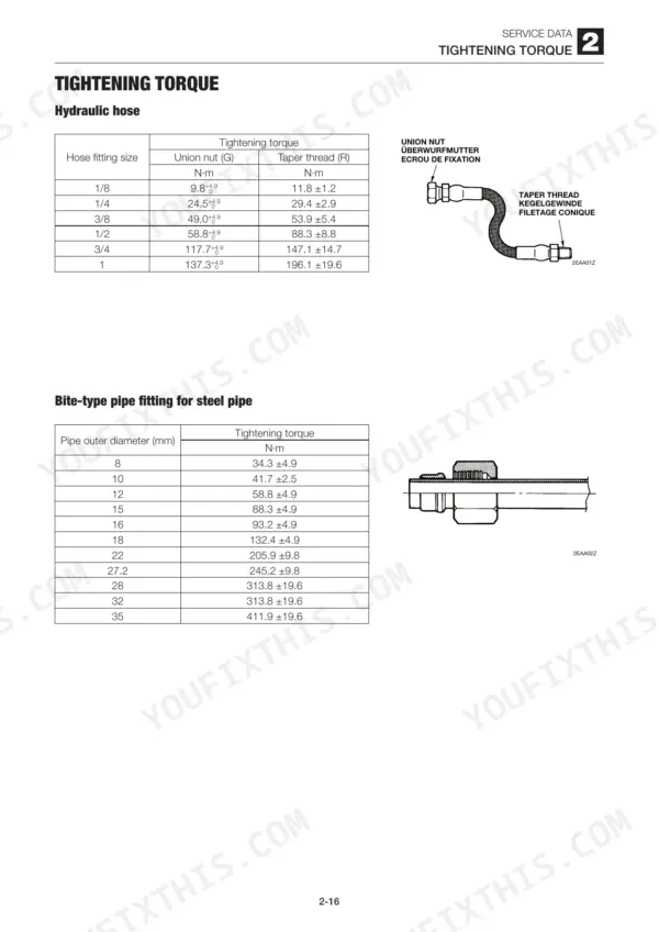
What is the tightening torque for the hydraulic hose union nut (G) with a 1/2 inch fitting on the Takeuchi TL240?
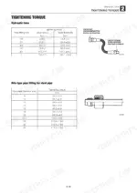
The tightening torque for a 1/2 inch hydraulic hose union nut (G) is 58.8 +4.9 N·m. p. 28
How do I bleed air from the HST pump?
After installing the HST pump, fill the servo control chambers with hydraulic oil through the pressure detection ports (M4, M5, M14, M15). Start the engine and let it run at an idling speed for five minutes to bleed air out of the pump casing. WARNING: Before reassembling the HST, be sure to bleed the air from it to avoid unexpected machine movement. p. 129
What is the correct crawler tension for the TL240?
The correct crawler tension for the TL240 is 25 to 50 mm. This measurement is taken between the central track roller and the top of the crawler shoe. p. 20
Will this Takeuchi TL240 Service Manual download right away?
One searchable PDF covering 344 pages, delivered instantly. No disc, no shipping, no waiting on the post.
Am I able to print pages from this Takeuchi TL240 manual?
Yes. It prints from any PDF reader, so run off the pages you need for your own repair work.