
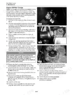
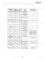
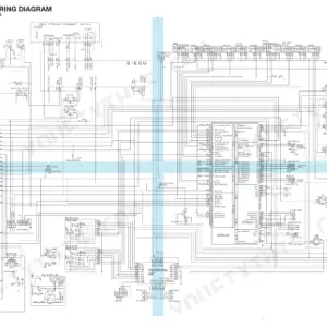
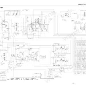
Within the hour your skid steer loader could be up on jack stands with the chain case open, and this 168-page Takeuchi TS50V, TS60V service manual PDF (OEM ID 7006-201) is the book to keep open beside it. Hydraulic circuit diagrams trace the drive, auxiliary and filter/cooling circuits through the lift arm control valve and solenoid block, while harness-by-harness wiring diagrams for both enclosed cab and open ROPS machines fill roughly the back third of the book. Removal and installation procedures follow the wear you see in the yard: tandem drive pump, drive motors, quick attach locking pins, lift arm bushings, tilt and lift cylinder seal kits and wheel pods. Set chain free play to 0.6 in. (15 mm), and confirm 450 psi (3103 kPa) at the charge pressure test port before touching the drive pumps. A pressure figure from memory can scrap a healthy pump. Print the sections you need and let them get greasy on the bench; the bookmarked PDF stays clean on your laptop.
What's Inside This Takeuchi TS50V, TS60V Manual
| System | Pages | Key Topics |
|---|---|---|
| Product Safety | 7-14 | Safety Messages, Information Messages, Basic Precautions, Safety Labels, Protective Equipment, Entering and Exiting, Lifting, Hot Fluids and Components |
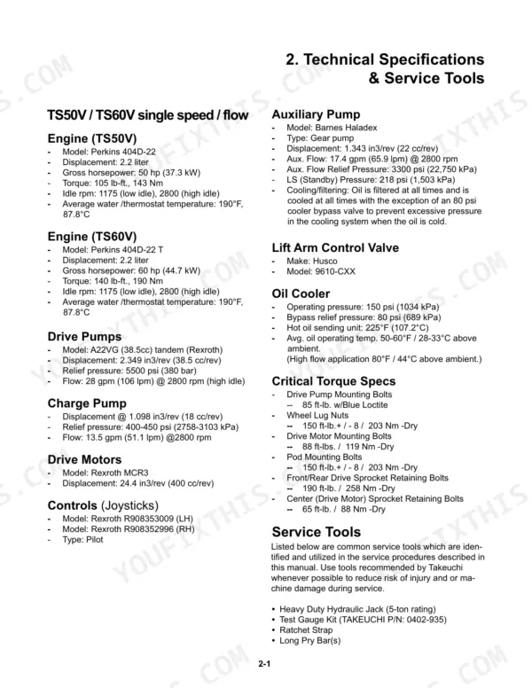
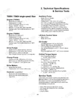
| Technical Specifications | 15-16 | Specifications Single Speed TS50V-TS60V (Engine, Drive Pumps, Charge Pump) |
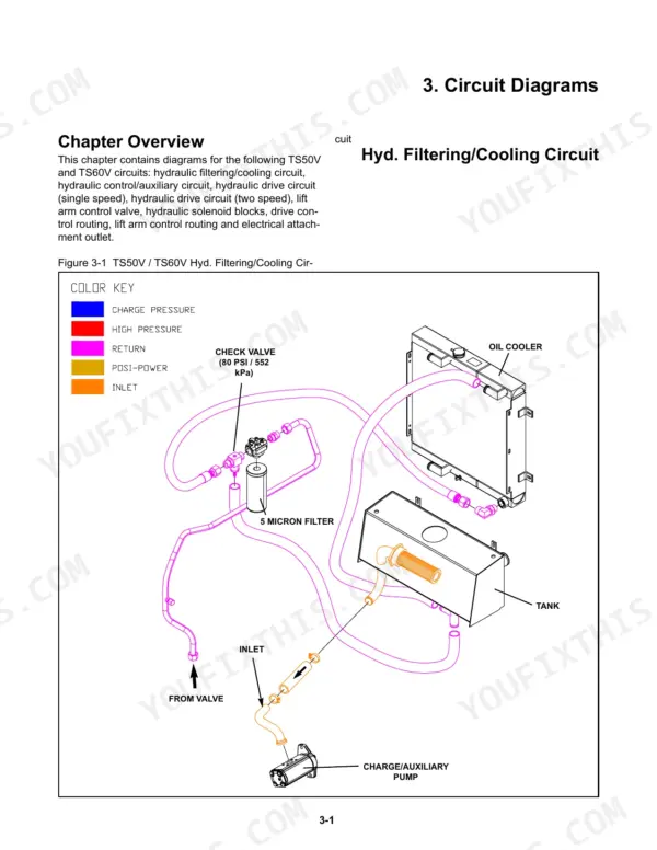
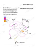
| Circuit Diagrams | 17-26 | Hydraulic Filtering / Cooling Circuit, Hydraulic Auxiliary Circuit, Hydraulic Drive Circuit, Lift Arm Control Valve, Hydraulic Solenoid Block, Electrical Attachment Outlet |
| Maintenance | 27-42 | Lift-Arm Brace, Tilt-Up Cab, Jacking Procedure, Grease Fittings, Tire Pressure, Chain Tension, Chain Tension Adjustment, Chain Case Oil Change |
| Machine Controls and Instrumentation | 43-44 | Machine Controls, Throttle, Instrumentation, Switches, Lift Arm Control, Drive Control |
| Operator Enclosure | 45-48 | Removal & Installation (Lap Bar Gas Spring, Removal Procedure, Installation Procedure, Dash Pod Cover, Side Panels/Gauges, Seat, Headliner), Machine Preparation, Personal Safety |
| Chassis and Fuel Tank | 49-54 | Removal & Installation (Fuel Sending Unit, Removal Procedure, Installation Procedure), Machine Preparation |
| Radiator and Oil Cooler | 55-58 | Removal & Installation (Fan and Fan Guard, Removal Procedure, Installation Procedure, Radiator/Oil Cooler), Machine Preparation, Personal Safety |
| Hydraulic Reservoir | 59-62 | Removal & Installation (Hydraulic Reservoir, Removal Procedure, Installation Procedure, Suction Screen), Machine Preparation, Personal Safety |
| Lift Arm/Drive Controls | 63-68 | Removal & Installation (Joystick, Removal Procedure, Installation Procedure, Lift Arm Float Magnet, Lift Arm Control Valve), Machine Preparation, Personal Safety |
| Hydraulic Pumps/Motors | 69-74 | Removal & Installation (Charge / Auxiliary Pump, Removal Procedure, Installation Procedure, Tandem Drive Pump, Drive Chain, Drive Motor), Machine Preparation, Personal Safety |
| Engine | 75-80 | Removal & Installation (Battery, Removal Procedure, Installation Procedure, Exhaust System, Air Cleaner, Engine), Machine Preparation, Personal Safety |
| Quick Attach | 81-84 | Removal & Installation (Locking Pin Assembly, Removal Procedure, Installation Procedure, Pivot Pin Assembly), Machine Preparation, Personal Safety |
| Lift Arm Components | 85-90 | Assembly & Disassembly (Lift Arm Linkage, Disassembly Procedure, Assembly Procedure) |
| Hydraulic Cylinder Service | 91-94 | Disassembly and Assembly (Tilt / Lift Cylinders Seal Kit, Disassembly Procedure, Assembly Procedure), Machine Preparation, Personal Safety |
| Wheel Pods | 95-100 | Disassembly and Assembly (Wheel Pod, Disassembly Procedure, Assembly Procedure), Machine Preparation, Personal Safety |
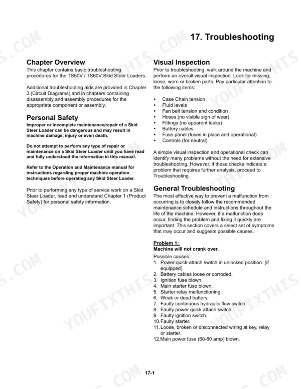
| Troubleshooting | 101-104 | Visual Inspection, Engine/Machine Troubleshooting, Personal Safety |
| Lubricant and Fuel Specifications | 105-106 | Fluids & Fuel Specifications |
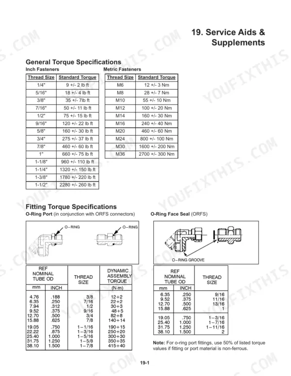
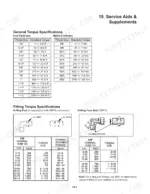
| Service Aids and Supplement | 107 | Fitting Torque Specifications |
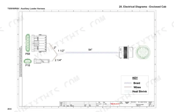
| Electrical Diagrams - Enclosed Cab | 108-145 | Overall Electrical Schematic, AC Condenser Harness, Auxiliary Loader Harness, Gauge Harness, Left Pillar Harness, Main Harness, Negative Battery Cable, Positive Battery Cable |
| Electrical Diagrams - ROPS | 146-168 | Overall Open ROPS Electrical Schematic, Open ROPS Cab Harness, Open ROPS Main Harness, Open ROPS Negative Battery Cable, Open ROPS Positive Battery Cable |
Every system also includes chapter overview.
Quick Reference Specifications
| Specification | Value | Page |
|---|---|---|
| All Models | ||
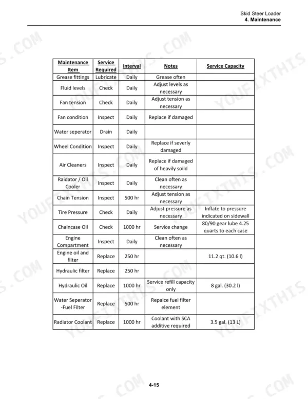
| Hydraulic oil capacity | 8 gal. (30.2 l) | p. 38 |
| Charge Pressure Test Port | 450 psi / 3103 kPa | p. 18 |
| Chain free play | 0.6 in. (15mm) | p. 30 |
| Engine oil capacity | 11.2 quarts (10.6 l) | p. 36 |
| Hydraulic Fluid Capacity | 8 gal. | p. 38 |
| Wheel Lug Nuts Torque | 150 ft-lb.+ / - 8 | p. 15 |
| Drive Motor Mounting Bolts Torque | 88 ft-lbs. | p. 15 |
| Front/Rear Drive Sprocket Retaining Bolts Torque | 190 ft-lb. | p. 15 |
| Center (Drive Motor) Sprocket Retaining Bolts Torque | 65 ft-lb. | p. 15 |
| Chain Case Oil Capacity | 4.25 quarts | p. 41 |
| TS50V | ||
| Engine Gross Horsepower | 50 hp | p. 15 |
| TS60V | ||
| Engine Gross Horsepower | 60 hp | p. 15 |
Takeuchi TS50V, TS60V Common Problems This Manual Covers
Takeuchi TS50V TS60V skid steer lift arms will not move and hydraulics will not operate
Check hydraulic fluid level first, then work through the hydraulics and lift arm steps of the troubleshooting on page 101. Test charge pressure at the charge pressure test port shown on the page 18 schematic against 450 psi (3103 kPa), and confirm the main relief valve setting of 3300 PSI from page 21.
Manual Section: General Troubleshooting p. 101Engine cranks but will not start, is hard to start, or runs low on power
Check the hard starting, no start and low power steps on page 103 before you replace parts. Remove and inspect the air cleaner elements, then clean or replace them. The removal procedure is in the engine section on page 75. If the engine will not crank at all, follow the no crank and battery charging steps on page 101.
Manual Section: Engine/Machine Troubleshooting p. 103Wheels will not move or drive chain runs slack inside the chain case
Check drive chain tension using the procedure on page 30 and measure free play against 0.6 in. (15 mm). Adjust it if it falls outside that figure. Change the chain case oil while you are in there, refilling with 4.25 quarts per page 41. If tension checks good, work through the wheels will not move steps on page 101.
Manual Section: Chain Tension Check and Adjustment p. 30Tilt or lift cylinder seals worn out and leaking hydraulic oil from the cylinder
Remove the cylinder and disassemble it following page 91, then install the tilt/lift cylinder seal kit and reassemble it using the same procedure. After installation, check the hydraulic fluid level and top it off. Total system capacity is 8 gal. (30.2 l) per page 38.
Manual Section: Hydraulic Cylinder Service p. 91Lift arm bushings and quick attach plate worn beyond limits with play in the linkage
Inspect the quick attach for wear and measure the lift arm bushings against the wear limits in the maintenance section. If a bushing is past its limit, replace it using the lift arm bushing removal and install procedure on page 85. Check the quick attach locking pin and pivot pin assemblies, and replace worn parts per page 81.
Manual Section: Lift Arm Components p. 85Wheel pod face seals leaking oil or bearings worn inside the wheel pod assembly
Disassemble the wheel pod following page 95, then inspect the bearings and face seals and replace any that are worn or damaged. Reassemble using the same procedure and add oil. Apply thread sealant to the fill plug and torque it to 12 +/- 2 ft lbs. as shown on page 100.
Manual Section: Wheel Pods p. 95Frequently Asked Questions
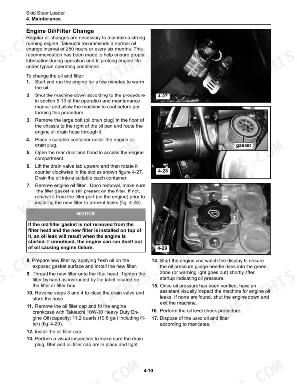
What are the engine oil filter replacement specs for the Takeuchi TS50V, TS60V skid steer?
Takeuchi recommends a normal oil change interval of 250 hours or every six months. The engine crankcase capacity is 11.2 quarts (10.6 liters) including the filter. When installing, apply fresh oil to the gasket surface and tighten by hand as instructed on the filter or filter box. p. 36
What are the fuel filter and water separator replacement specs for the Takeuchi TS50V, TS60V?
The fuel filter should be changed every 500 hours or more often if needed. The water separator should be drained daily to maintain proper function. p. 33
How do you bleed the hydraulic system on a Takeuchi TS50V or TS60V?
After changing the hydraulic fluid and filter, start the machine and operate all hydraulic circuits to work any trapped air out of the system. This includes driving the machine forward and backward, raising and lowering the lift arms (unloaded), and dumping and curling the bucket/quick attach. p. 38
What is the correct torque specification for the wheel lug nuts on the Takeuchi TS50V, TS60V?
The wheel lug nuts must be tightened to 150 ft-lb (+/- 8) or 203 Nm (dry). p. 15
What is the correct torque spec for the front/rear drive sprocket retaining bolts on a Takeuchi TS50V, TS60V?
The front/rear drive sprocket retaining bolts must be tightened to 190 ft-lb or 258 Nm (dry). p. 15
Will this Takeuchi TS50V Service Manual download right away?
One searchable PDF covering 168 pages, delivered instantly. No disc, no shipping, no waiting on the post.
Am I free to print this Takeuchi TS50V Service Manual?
Yes. Print individual pages or full chapters for your own shop use, on letter or A4 paper.
Reviews
There are no reviews yet.