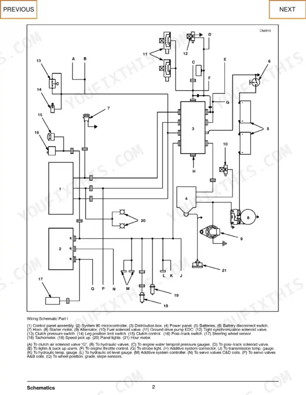
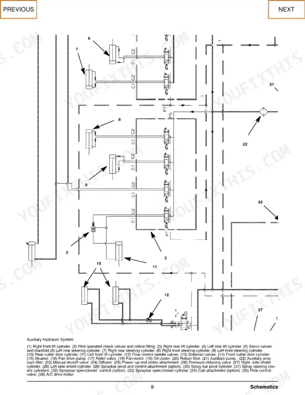
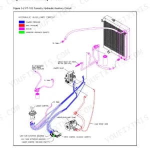
From the primary power system and ground drive through the cutter and cutter gearbox, this 399-page Terex RS-800 service manual PDF (OEM ID A08315-E02) walks the reclaimer/stabilizer end to end, controls and maintenance included. Electrical schematics come with a components locator. Hydraulic schematics trace the auxiliary and ground drive circuits. The pressure settings section lists auxiliary, ground drive charge, fan drive relief and cutter belt tensioner values, and the Controls chapter explains the microcontroller's calibrate and setup display modes. Expect charge pressure of 206.85 kPa (30 psi), and torque a 16 mm worm drive hose clamp to 7.5 ± 0.5 Nm on initial installation and 3.0 ± 0.5 Nm when retightening. For the fan drive relief check, you want the hydraulic oil warm (approximately 130° F), the engine at low idle and the pump dead headed. With bookmarks and searchable text, your cutter gearbox replacement gets done to Terex's own figures.
What's Inside This Terex RS-800 Manual
| System | Pages | Key Topics |
|---|---|---|
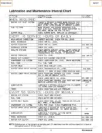
| Forward | 5-6 | Operation Instructions, Lubrication Information, Maintenance Information, Service Meter, Maintenance Interval Chart |
| Safety | 7-22 | General, Warning Signs and Labels, Basic Guidelines, Asbestos Dust, Push-Pull Control Cables, Crushing or Cutting Prevention, Burn Prevention, Fire or Explosion Prevention |
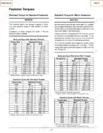
| Torque Specifications | 23-28 | Fastener Torques |
| Hydraulic Pressure Settings | 29-30 | Auxiliary System Pressure, Ground Drive Charge Pressure, Fan Drive Relief Setting, Cutter Belt Tensioner Pressure, Cutter Transmission Oil Cooling Bypass, Tire Pressure |
| Receiving and Transporting the Machine | 31-42 | Shipping, Unload the Machine |
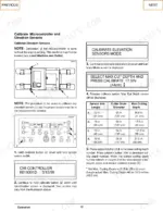
| Controls | 43-92 | Control Console, Microcontroller, Normal Display Mode, Calibrate Display Mode, Sensitivity Display Mode, Miscellaneous Display Mode, Setup Display Mode |
| Operation | 93-180 | Before Engine Start, Start the Engine, Operating Adjustments, Operating Techniques for Work in Soil |
| Maintenance | 181-242 | Maintenance Recommendations, Service Intervals |
| Component Replacement | 243-374 | Primary Power System, Ground Drive System, Cutter, Cutter Gearbox |
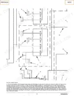
| Schematics | 375-386 | Electrical Schematic, Electrical Components Locator, Auxiliary Hydraulic System, Ground Drive Hydraulic System |
| Technical Reference | 387-399 | Technical Terms, Common Symbols |
Quick Reference Specifications
| Specification | Value | Page |
|---|---|---|
| Charge pressure | 206.85 kPa (30 psi) | p. 267 |
| Hose Clamps - Worm Drive Band Type (16 mm) Initial Installation Torque | 7.5 ± 0.5 Nm | p. 25 |
| Hose Clamps - Worm Drive Band Type (13.5 mm) Initial Installation Torque | 4.5 ± 0.5 Nm | p. 25 |
| Cutter override switch engagement height | 6 in (15 cm) | p. 138 |
| Primary fuel filter retaining bolt torque | 18 ± 5 lb ft (24 ± 7 Nm) | p. 199 |
| Fuel line nut torque | 30 ± 5 lb ft (40 ± 7 Nm) | p. 200 |
| Cutter bit wear limit | 1.2 in (30 mm) | p. 201 |
| Left side cutter belt tensioning pressure | 7700 psi (53091.5 kPa) | p. 216 |
| Right side cutter belt tensioning pressure | 6600 psi (45507 kPa) | p. 216 |
| Tire pressure (standard) | 30 psi (207 kPa) | p. 214 |
| Tire pressure (cold weather) | 41 psi (282 kPa) | p. 214 |
Terex RS-800 Common Problems This Manual Covers
Terex RS-800 steering wheel sensor and wheel steering sensors out of calibration, wheels not tracking correctly
Check the steering wheel sensor with the ignition ON and the wheel spring-centered; page 122 calls for 3.95 to 4.05V. Outside that window, rotate the sensor housing to exactly 4.00V. Then check the flexible drive setscrews and align each wheel to a stringline until front and rear sidewall measurements fall within 1/8 in (3.2 mm).
Manual Section: Steering Sensor Calibration p. 122Low Charge Pressure fault flashing on the microcontroller display, propel pump charge pressure below minimum
Measure propel pump charge pressure. The fault on page 92 trips below 300 psi (2068.5 kPa), and page 29 sets ground drive charge pressure at 400 psi. Relieve all pressure before loosening any line or fitting (page 16), and never check for leaks with a bare hand (page 17); escaping hydraulic fluid can penetrate skin (page 13).
Manual Section: Fault Diagnostics p. 92Change Hydraulic Filter warning showing on the microcontroller, pressure filter restriction at maximum
Replace both hydraulic filters. Page 92 sets this warning at 50 psi (344.75 kPa) of restriction in the pressure hydraulic circuit. Relieve all pressure in the oil system before loosening any filter or fitting, and keep hot oil and hot components off your skin (page 16). Check the hydraulic oil level after the change.
Manual Section: Fault Diagnostics p. 92Steer or elevation servo fault displayed, servo valve coil showing open or short circuit
Measure the coil resistance of the servo valve named on the fault screen. Page 91 flags an open circuit above 40,000 ohms and a short to ground below 10 ohms. Command that steer or elevation function while watching the display, because the microcontroller only diagnoses a coil while a signal is being sent to it.
Manual Section: Fault Diagnostics p. 91Steering or elevation sensor fault on screen, sensor voltage reading out of range
Check the 8V sensor supply first, because its fault screen overrides sensor faults; page 90 sets the range at 7.5 to 8.5V. Then read the named sensor against the 1.75V to 6.25V window on page 91. A good supply with a bad reading means the sensor is out of calibration or has an open or short circuit.
Manual Section: Fault Diagnostics p. 91Water temperature or oil pressure sender fault displayed, sender reading open or shorted
Measure the resistance of the sender named on the fault screen. Page 91 reports an open circuit above 25,000 ohms and a short to ground below 5 ohms for the transmission temperature, water temperature, hydraulic oil temperature and engine oil pressure senders. Never switch to None (Ignore Faults) Mode to keep running (page 87).
Manual Section: Fault Diagnostics p. 91Frequently Asked Questions
What are the torque specifications for standard bolts and nuts on the RS-800?
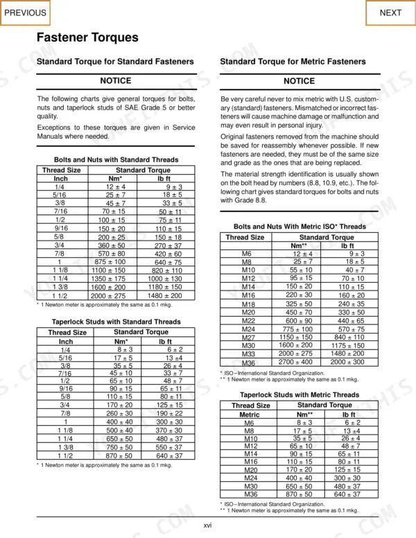
The torque specifications for standard bolts and nuts vary by size. For example, a 1/4 inch bolt requires 12 ± 4 Nm (9 ± 3 lb ft), while a 1/2 inch bolt requires 100 ± 15 Nm (75 ± 11 lb ft). A 1 inch bolt requires 875 ± 100 Nm (640 ± 75 lb ft). p. 24
How do I reset the microcontroller parameters on the RS-800?
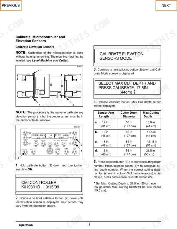
To reset the microcontroller parameters, enter the Setup Display Mode by holding the calibrate button (4) down, pressing and releasing the sensitivity button (5) twice, and then releasing the calibrate button. Scroll through all Setup screens and reset the parameters to the default values listed on page 139. p. 139
What is the procedure for checking the engine oil level?
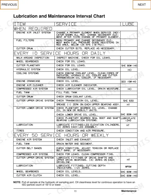
Check the engine oil level on the ENGINE STOPPED side of the dipstick. Maintain the oil level between the FULL and ADD marks. Always check the level after the engine has been stopped for about 10 minutes to allow the oil to drain back to the crankcase. p. 207
What is the proper belt deflection for the alternator drive belt?
For a used belt, the proper deflection is 7/8 inch (22 mm). For a newly installed belt, the deflection should be 1/2 to 3/4 inch (12.5 to 19 mm). Apply a force of 25 lb (11 kg) perpendicular to the belt midway between the pulleys to measure this. p. 223
What is the procedure for changing the hydraulic oil in the hydraulic system?
Close the valves (1) and disconnect the hoses. Drain the tank completely by removing the drain plug at the bottom of the hydraulic oil tank (2). Clean the tank, replace the drain plug, reconnect the hoses, and fill the tank with clean, water-free hydraulic oil as specified in the Refill Capacities section. p. 241
How quickly can I access this Terex RS-800 manual after buying?
One searchable PDF covering 399 pages, delivered instantly. No disc, no shipping, no waiting on the post.
Am I able to print pages from this Terex RS-800 manual?
Yes. Print the sections you need to take out to the shop for your own use. Standard letter or A4 paper works.