
Charge, drive and Posi-Power pressure checks on the hydrostatic system anchor the Terex PT-100 Forestry service manual PDF, a 94-page book (OEM ID 2085-249) for this rubber track loader that widens to pump, undercarriage, radiator and loader valve teardown. Hydraulic schematics trace the charge, auxiliary and drive circuits through the lift arm control valve and pilot gen block, and a wiring diagram maps the electrical attachment outlet. Maintenance takes up roughly a quarter of the book, running from the air cleaner and grease fittings through drive belt tension, cooler air flow testing and fan cleaning to the maintenance schedule. Set track tension at 3/4 in (1.9 cm) to 1 in (2.5 cm) of deflection under 90 lbs (41 kg) of down force; drive pump relief sits at 5500 psi (380 bar). A made-up relief figure finds your weakest hose first. Bought once, the bookmarked, text-searchable PDF stays yours for as long as this loader is in your fleet.
What's Inside This Terex PT-100 FORESTRY Manual
| System | Pages | Key Topics |
|---|---|---|
| Product Safety | 5-10 | Basic Precautions (Safety Labels, Personal Protective Equipment, Entering and Exiting) |
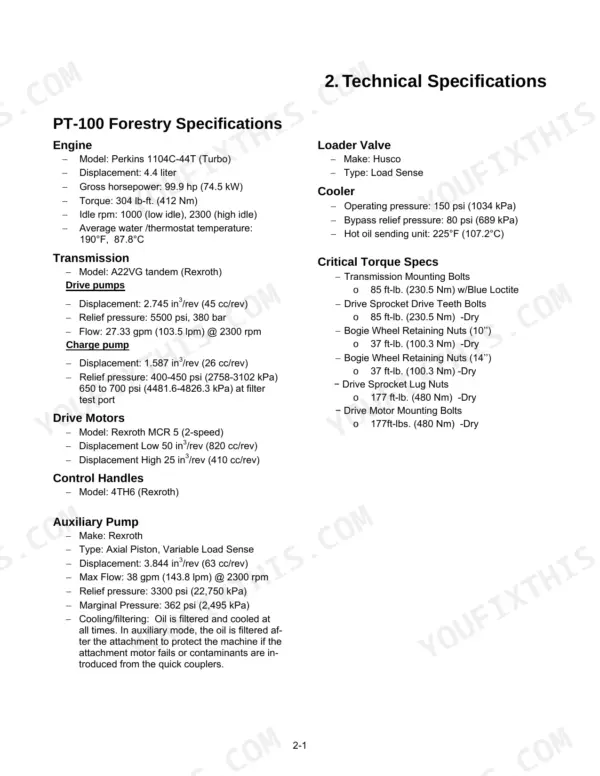
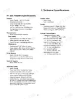
| Technical Specifications | 11-12 | Specifications (Engine, Transmission, Drive Motors), Loader Valve, Critical Torque Specs, Charge Pump |
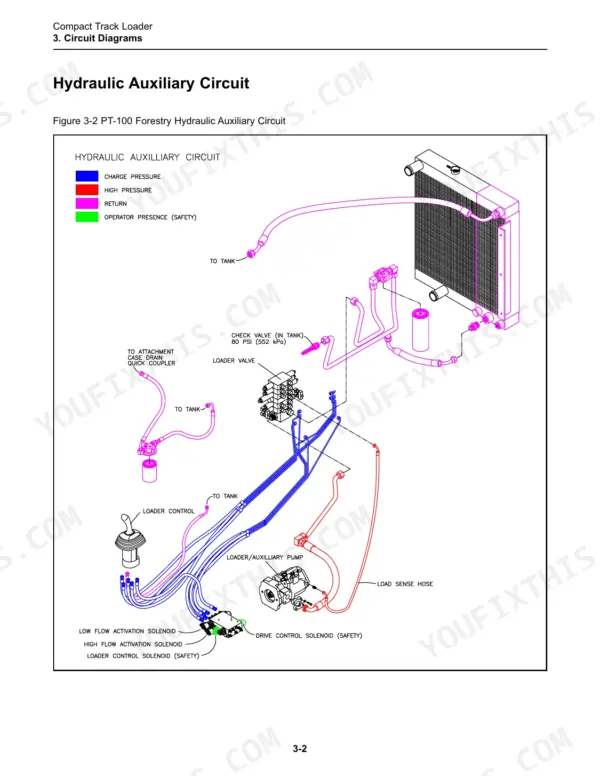
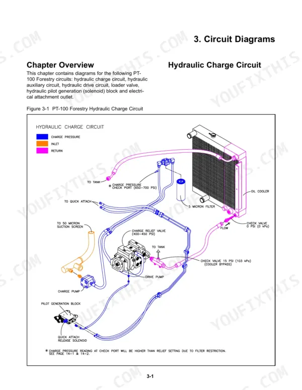
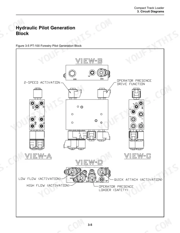
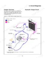
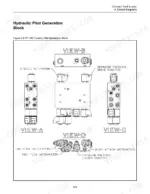
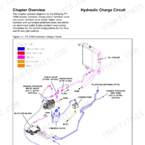
| Circuit Diagrams | 13-18 | Hydraulic Charge Circuit, Hydraulic Auxiliary Circuit, Hydraulic Drive Circuit, Lift Arm Control Valve, Hyd. Pilot Gen Block, Electrical Attachment Outlet |
| Machine Controls and Instrumentation | 19-20 | Machine Controls (Loader Control, Drive Control, Throttle), Instrumentation, Switches |
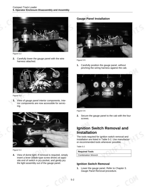
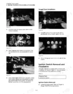
| Operator Enclosure Disassembly and Assembly | 21-26 | Operator Enclosure Disassembly and Assembly Procedures, Gauge Panel Removal and Installation, Ignition Switch Removal and Installation, Gauge Removal and Installation |
| Fuel Tank Disassembly and Assembly | 27-30 | Disassembly and Assembly Procedures, Fuel Sending Unit Removal & Installation, Fuel Tank Removal, Fuel Tank Installation, Machine Preparation, Personal Safety |
| Radiator/Oil Cooler Disassembly and Assembly | 31-36 | Radiator/Oil Cooler Disassembly and Assembly Procedures, Fan Guard Removal and Installation, Fan Removal, Fan Installation, Radiator/Cooler Removal, Radiator/Cooler Installation |
| Loader/Transmission Controls Disassembly and Assembly | 37-40 | Loader/Transmission Controls Disassembly and Assembly Procedures, Joystick Removal and Installation, Loader Float Magnet Removal and Installation, Machine Preparation |
| Hydrostatic & Aux. Pump Disassembly and Assembly | 41-46 | Hydrostatic & Hydraulic Pump Disassembly and Assembly Procedures, Charge Pump Removal, Auxiliary Pump Removal, Auxiliary Pump Installation, Tandem Pump Removal |
| Undercarriage Disassembly and Assembly | 47-52 | Undercarriage Disassembly and Assembly Procedures, Sprocket Removal and Installation, Drive Motor Removal, Drive Motor Installation, Wheel Replacement, Wheel Installation |
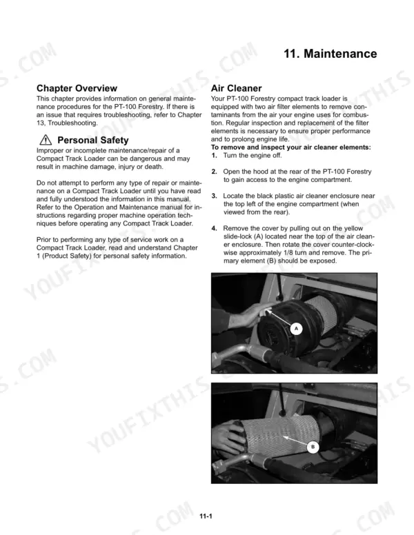
| Maintenance | 53-76 | Air Cleaner, Grease Fittings, Undercarriages (Track Tension), Drive Sprocket Rollers, Tilt-Up Canopy (Jacking Procedure), Lift Arm Brace, Track Removal (Track Installation) |
| Lubricant & Fuel Specifications | 77-78 | Engine Oil, Engine Anti-Freeze/Coolant, Hydraulic Oil, Multi-Purpose EP Lithium Grease, Undercarriage Wheel Bearing Lube, Diesel Fuel |
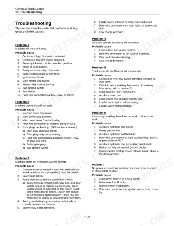
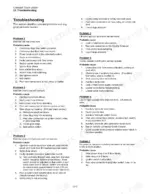
| Troubleshooting | 79-82 | Preliminary Checkout (Visual Inspection), Troubleshooting Scenarios, Machine Preparation, Personal Safety |
| Hydraulic Pressure (Check & Adjustment) | 83-88 | Charge Pressure Check & Adjustment, Auxiliary Pressure Check & Adjustment (High Flow Troubleshooting), Low Flow Troubleshooting (Lift Arm Pressure Check) |
| Hydraulic Cylinder & Loader Valve | 89-94 | Disassembly & Assembly, Hydraulic Cylinder Disassembly, Hydraulic Cylinder Assembly, Loader Valve Disassembly, Loader Valve Assembly, Personal Safety |
Every system also includes chapter overview.
Quick Reference Specifications
| Specification | Value | Page |
|---|---|---|
| Drive pumps Relief pressure | 5500 psi, 380 bar | p. 11 |
| Auxiliary Pump Relief pressure | 3300 psi (22,750 kPa) | p. 11 |
| Track tension deflection | 3/4" (1.9 cm) to 1" (2.5 cm) | p. 55 |
| Track tension check down force | 90 lbs (41 kg) | p. 55 |
| Hot oil light illumination temperature | 225°F (107.5°C) | p. 81 |
| Cooler bypass relief opening pressure | 80 PSI (561.7 kPa) | p. 81 |
| Engine Torque | 304 lb-ft (412 Nm) | p. 11 |
| Engine Idle RPM (Low) | 1000 rpm | p. 11 |
| Engine Idle RPM (High) | 2300 rpm | p. 11 |
| Engine Oil Capacity | 8.5 U.S. quarts (8.04 L) | p. 64 |
| Hydraulic System Oil Capacity | 20 U.S. gallons (75.71 L) | p. 77 |
| Hydraulic Fluid Change Interval | 500 hours | p. 66 |
Terex PT-100 FORESTRY Common Problems This Manual Covers
Terex PT-100 Forestry rubber track loader engine will not crank over when turning the ignition key
Start with the preliminary checkout visual inspection, then work through the will-not-crank scenario in the troubleshooting section on page 79. Trace the starting circuit on the wiring diagram on page 17 instead of guessing at parts. If the ignition switch itself is suspect, pull it using the operator enclosure procedure beginning on page 21.
Manual Section: Troubleshooting p. 79Engine starts and runs but hydraulics will not operate at the loader controls
Work through the hydraulics-will-not-operate scenario in the troubleshooting section starting on page 79 before you open any lines. Check charge pressure following the procedure on page 83. Then trace the hydraulic charge circuit and the hydraulic pilot gen block on the schematic on page 13 to find where the oil stops.
Manual Section: Troubleshooting p. 79Lift arms operate normally but tracks will not move when the drive control is pushed
Run the lift-arms-operate-but-tracks-will-not-move scenario in the troubleshooting section starting on page 79. Check drive pressure following the hydraulic pressure procedure on page 83 and compare it to the 5500 psi (380 bar) drive pump relief setting listed on page 11. Trace the hydraulic drive circuit on the schematic starting at page 13 before you pull a drive motor.
Manual Section: Troubleshooting p. 79Auxiliary hydraulics weak or dead at the attachment in high flow or low flow
Check auxiliary pressure following the check and adjustment procedure on page 83, which includes high flow and low flow troubleshooting. Compare the reading to the 3300 psi (22,750 kPa) auxiliary pump relief spec on page 11. If the attachment has no power at all, trace the electrical attachment outlet circuit on the wiring diagram on page 17.
Manual Section: Hydraulic Pressure (Check & Adjustment) p. 83Hot oil light comes on during heavy work and the hydraulic oil runs hot
Verify the oil is actually hot: the hot oil light comes on at 225°F (107.5°C), per page 81. Check that the cooler bypass relief opens at 80 PSI (561.7 kPa). Then run the radiator/oil cooler air flow test. If the cooler has to come out, follow the fan guard and radiator/cooler removal starting on page 31.
Manual Section: Troubleshooting p. 81Rubber tracks sagging loose between drive sprocket and front idler with worn sprocket rollers
Measure tension by hanging 90 lbs (41 kg) midway between the drive sprocket and front idler, per page 55. Deflection should fall between 3/4" (1.9 cm) and 1" (2.5 cm) on the same page. Inspect sprocket rollers every 50 hours and replace any that are cracked or worn below 35% of original thickness (.088" or .22 cm), following page 56.
Manual Section: Maintenance p. 55Frequently Asked Questions
What causes a PT-100 Forestry to crank but not start?
If the machine cranks but will not start, check for a blown injection pump fuse, blown main power fuse B, or a malfunctioning main power relay B. Additionally, verify the glow plugs are heating; if they are not, check for a blown main glow plug fuse, a failed glow plug relay, or faulty glow plugs as described in the troubleshooting section. p. 80
What is the recommended engine oil change interval for the PT-100 Forestry?
Terex recommends a normal engine oil change interval of 250 hours or every six months to ensure proper lubrication and prolong engine life under typical operating conditions. p. 63
What is the correct torque specification for the transmission mounting bolts on the Terex PT-100 Forestry?
The transmission mounting bolts should be tightened to 85 ft-lb. (230.5 Nm) using Blue Loctite. p. 11
How do I check the track tension on the PT-100 Forestry?
To check track tension, drive the machine forward 5 feet (1.5 m) to remove slack, lay a straight edge along the top of the track, and apply 90 lbs (41 kg) of down force midway between the drive sprocket and front idler. The deflection should measure between 3/4 inch (1.9 cm) and 1 inch (2.5 cm). p. 55
What is the capacity of the hydraulic system for the PT-100 Forestry?
The hydraulic system capacity for the PT-100 Forestry is 20 U.S. gallons (75.71 L), which includes the filters. p. 77
What exactly do I receive with this Terex PT-100 Forestry Service Manual?
Delivery is instant: a 94-page searchable PDF is yours the second checkout clears. Laptop, tablet, or phone, all fine.
Is printing allowed for this Terex PT-100 Forestry Service Manual?
Yes. Print individual pages or full chapters for your own shop use, on letter or A4 paper.



Reviews
There are no reviews yet.