
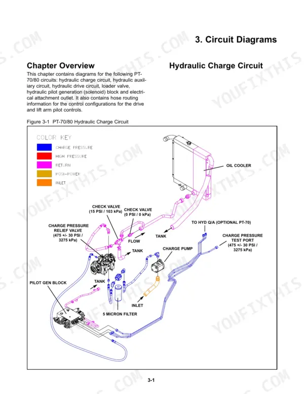
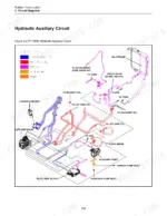
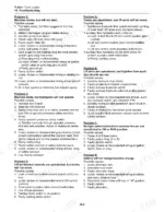
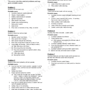
The undercarriage, tandem drive pump, lift arm control valve, drive motors and quick attach each run from removal through reinstallation in this 141-page Terex PT-70, PT-80 service manual PDF (OEM ID 2046-310) for both rubber track loaders. Hydraulic circuit diagrams trace the charge, auxiliary and drive circuits and the pilot generation solenoid block, while a separate drawing covers the electrical attachment outlet. Pressure testing and hydraulic rebuilds fill a good share of the book, taking you through charge, auxiliary and Posi-Power checks before you split a drive pump or motor brake. Replace motor brake clutch discs as a set if any measures under .015 in (.38 mm); tandem pump mounting bolts go back at 85 lb-ft (115 Nm). Alone with a stalled loader, there is nobody to ask. Bookmarked chapters and a searchable text layer help you pin down the exact pump or valve, so the part you order is right the first time.
What's Inside This Terex PT-70, PT-80 Manual
| System | Pages | Key Topics |
|---|---|---|
| Product Safety | 7-12 | Safety Messages, Information Messages, Basic Precautions, Safety Labels, Protective Equipment, Entering and Exiting, Lifting, Hot Fluids and Components |
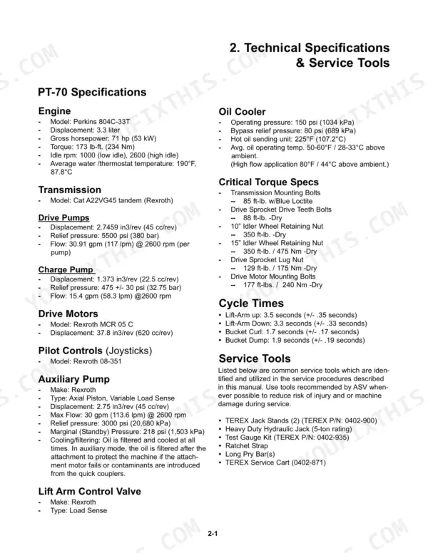
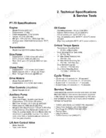
| Technical Specifications | 13-14 | Specifications (Engine, Transmission, Drive Pumps) |
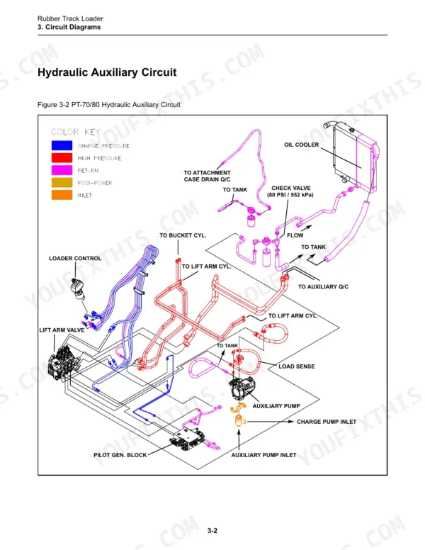
| Circuit Diagrams | 15-22 | Hydraulic Charge Circuit, Hydraulic Auxiliary Circuit, Hydraulic Drive Circuit, Lift Arm Control Valve, Hydraulic Pilot Generation Solenoid Block, Electrical Attachment Outlet |
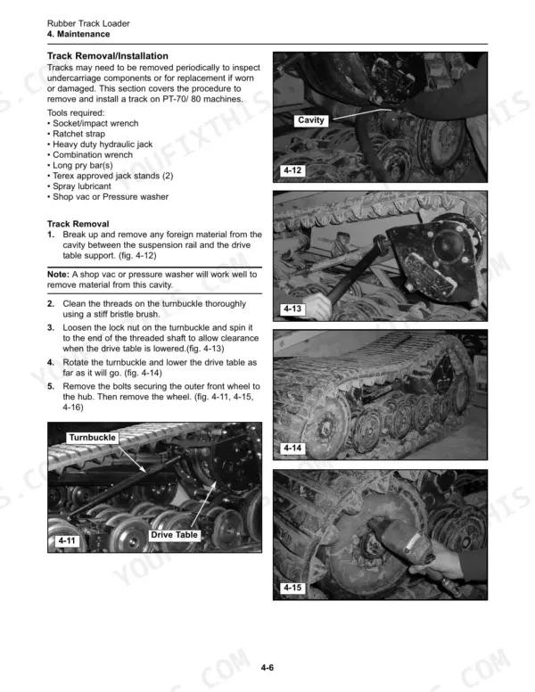
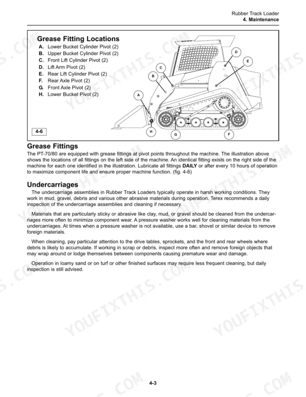
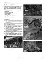
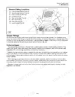
| Maintenance | 23-42 | Lift-Arm Brace, Tilt-Up Cab, Jacking Procedure, Grease Fittings, Undercarriages, Track Tension, Drive Sprocket Rollers, Track Removal |
| Machine Controls and Instrumentation | 43-44 | Machine Controls, Throttle, Instrumentation, Switches, Lift Arm Control, Drive Control |
| Operator Enclosure | 45-48 | Machine Preparation, Removal & Installation (Door Gas Spring, Removal Procedure, Installation Procedure) |
| Chassis and Fuel Tank | 49-54 | Machine Preparation, Removal & Installation (Fuel Sending Unit, Removal Procedure, Installation Procedure, Fuel Tank, Footwell, Foot Throttle Assembly, Hood Assembly) |
| Radiator and Oil Cooler | 55-58 | Machine Preparation, Removal & Installation (Fan Guard, Removal Procedure, Installation Procedure, Fan & Shroud, Radiator/Oil Cooler), Personal Safety |
| Hydraulic Reservoir | 59-66 | Machine Preparation, Removal & Installation (Hydraulic Reservoir, Removal Procedure, Installation Procedure, Suction Screen), Personal Safety |
| Lift Arm/Drive Controls | 67-70 | Machine Preparation, Removal & Installation (Joystick, Removal Procedure, Installation Procedure, Lift Arm Float Magnet, Lift Arm Control Valve), Personal Safety |
| Hydraulic Pumps/Motors | 71-78 | Machine Preparation, Removal & Installation (Charge Pump, Removal Procedure, Installation Procedure, Auxiliary Pump, Tandem Drive Pump, Drive Motor), Personal Safety |
| Engine | 79-86 | Removal & Installation (Battery, Removal Procedure, Installation Procedure, Exhaust System, Air Cleaner, Engine), Personal Safety |
| Undercarriage | 87-98 | Machine Preparation |
| Lift Arm Components | 99-104 | Machine Preparation, Removal & Installation (Lift Cylinder, Removal Procedure, Installation Procedure, Bucket/Tilt Cylinder, Q/C Block PRV), Personal Safety |
| Quick Attach | 105-108 | Machine Preparation, Removal & Installation (Locking Pin, Removal Procedure, Installation Procedure, Pivot Pin), Personal Safety |
| Hydraulic Component Service | 109-124 | Disassembly & Assembly (Hydraulic Cylinder, Disassembly Procedure, Assembly Procedure) |
| Hydraulic Pressure & Flow | 125-132 | Contamination Inspection |
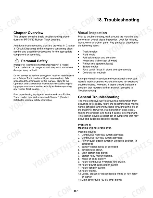
| Troubleshooting | 133-136 | Visual Inspection, Engine/Machine Troubleshooting, Personal Safety |
| Lubricant and Fuel Specifications | 137-141 | Fluids & Fuel Specifications |
Every system also includes chapter overview.
Quick Reference Specifications
| Specification | Value | Page |
|---|---|---|
| All Models | ||
| Tandem pump mounting bolts torque | 85 lb. ft. (115 Nm) | p. 75 |
| Inch Fasteners 1/4" Torque | 9 +/- 2 lb ft | p. 139 |
| Clutch disc wear limit | less than .015” (.38mm) | p. 115 |
| Engine Oil Capacity | 9 qt. / 8.5l | p. 41 |
| Hydraulic Fluid Service Refill Capacity | 12.25 gal. / 46.4l | p. 41 |
| Radiator Coolant Capacity | 3.125 gal. / 11.8l | p. 41 |
| PT-70 | ||
| Engine Gross Horsepower | 71 hp (53 kW) | p. 13 |
| PT-80 | ||
| Engine Gross Horsepower | 80 hp (60 kW) | p. 14 |
Terex PT-70, PT-80 Common Problems This Manual Covers
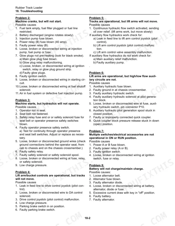
Terex PT-70 PT-80 lift arm and bucket controls work but tracks will not move
Check drive pressure and charge pressure using the hydraulic test procedures on page 125 before pulling anything. If pressures are off, inspect the tandem drive pump and drive motor per the Hydraulic Component Service section. Measure each drive motor clutch disc; if any disc reads less than .015" (.38mm), replace them as a set.
Manual Section: General Troubleshooting p. 133High flow or low flow auxiliary hydraulic circuit not operational at the attachment
Test auxiliary valve pressure and run the auxiliary flow test following page 125 before swapping parts. If flow comes up short, inspect the auxiliary pump using the Hydraulic Component Service disassembly procedures. Trace the plumbing against the hydraulic auxiliary circuit diagram in the schematics starting on page 15 so you know which valve feeds which coupler.
Manual Section: General Troubleshooting p. 133With tracks driving normally, lift arms will not move when the joystick is pushed
Test lift arm pressure following the procedure on page 125 before tearing into the valve. If pressure is low, inspect the lift arm control valve per the removal steps on page 67, then service it using the Hydraulic Component Service disassembly procedures on page 109. Keep the valve spools clean and in order on the bench.
Manual Section: General Troubleshooting p. 133Lift arm control joystick float lock will not hold the lift arms in float position
Inspect the lift arm float magnet using the removal and installation steps on page 67. If the magnet checks out, work through the lift arm float and down pressure checks in the engine/machine troubleshooting chart on page 135 before touching the lift arm control valve.
Manual Section: Engine/Machine Troubleshooting p. 135During a normal day of loading, hydraulic oil temperature gauge reads high
Inspect the radiator/oil cooler, fan and fan shroud, following the removal steps on page 55 if the core needs to come out. Inspect the suction screen in the hydraulic reservoir per page 59. Refill with 12.25 gal. (46.4l), the hydraulic fluid service refill capacity, after servicing the screen.
Manual Section: Engine/Machine Troubleshooting p. 135Engine cranks but will not start, or starts hard and shows low power
Check the hard starting, low power and no start items in the engine/machine troubleshooting chart on page 135. Inspect the air cleaner and battery using the Engine section procedures starting on page 79. Verify your fuel meets the fuel specifications starting on page 137 before suspecting internal engine faults.
Manual Section: Engine/Machine Troubleshooting p. 135Frequently Asked Questions
What are the replacement specifications for the hydraulic drive motor on the Terex PT-70, PT-80?
The drive motor for the PT-70 is the Rexroth MCR 05 C with a displacement of 37.8 in3/rev (620 cc/rev). The PT-80 uses the Rexroth MCR 5 (2-speed) with a displacement of 50 in3/rev (820 cc/rev). p. 13
How often should I change the engine oil and filter on a Terex PT-70, PT-80?
Terex recommends a normal oil change interval of 250 hours or every six months to ensure proper lubrication and prolong engine life under typical operating conditions. p. 36
What is the correct hydraulic fluid capacity for the PT-70/80?
The service refill capacity for the hydraulic system is 12.25 gallons (46.4 liters). p. 41
What air pressure should I use to clean the radiator or oil cooler on a Terex PT-70, PT-80?
When using compressed air to clean the radiator or oil cooler, the nozzle must be at least 8 inches (20.3 cm) away from the cooler to prevent damage to the cooling fins. p. 39
Is this Terex PT-70 manual a download or a disc?
Delivery is instant: a 141-page searchable PDF is yours the second checkout clears. Laptop, tablet, or phone, all fine.
Is this Terex PT-70 manual print-friendly?
You can. The PDF is unlocked and carries no copy protection, so print the sections you want and keep the file as your backup.
Does this Terex PT-70 manual show the machine's wiring?
Partly. The electrical coverage is one diagram of the electrical attachment outlet on page 20; the rest of the Circuit Diagrams chapter covers the hydraulic circuits.


Reviews
There are no reviews yet.