
The Terex PT-30 service manual PDF (OEM ID 2010-513) strips the PT-30 compact track loader down to its tandem pump, drive motors and lift cylinders, then builds it back up across 116 pages. Hydraulic schematics lay out the drive loop, auxiliary circuit and filtering and cooling system, so you can trace oil through each circuit before you crack a fitting. Disassembly and assembly procedures fill most of the book, from the loader valve and quick-attach latch pins to sprocket bearing plates, track removal and lift arm bushings, and a final chapter walks you through charge, drive and auxiliary pressure checks and adjustments. Check drive pump relief against 3800 psi (26,200 kPa), and on serial 05001 and up, torque the drive sprocket castle nut to 270 ft-lb (366 Nm). Each day a loader sits on blocks, it earns nothing. Bookmarked and text-searchable, the file goes with you on a laptop or phone to wherever the PT-30 is parked.
What's Inside This Terex PT-30 Manual
| System | Pages | Key Topics |
|---|---|---|
| Product Safety | 8-13 | Basic Precautions, Safety Labels, Personal Protective Equipment, Entering and Exiting, Lifting, Hot Fluids and Components, Corrosion Inhibitor, Batteries |
| Technical Specifications | 14-15 | Pt-30 Specifications |
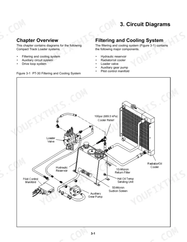
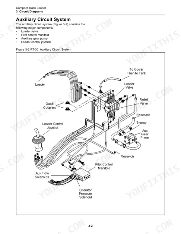
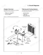
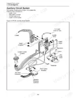
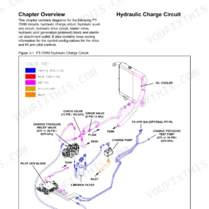
| System Diagrams | 16-19 | Filtering and Cooling System, Auxiliary Circuit System, Drive Loop System |
| Machine Controls and Instrumentation | 20-21 | Machine Controls (Loader Control, Drive Control, Throttle), Instrumentation, Switches |
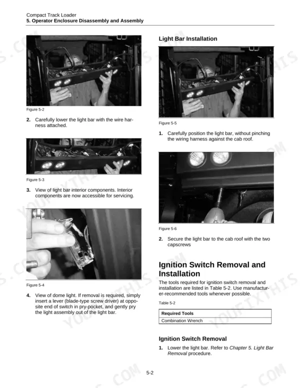
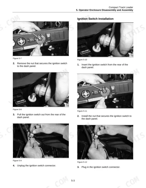
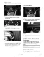
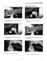
| Operator Enclosure Disassembly and Assembly | 22-27 | Operator Enclosure Disassembly and Assembly Procedures, Light Bar Removal and Installation, Ignition Switch Removal and Installation, Gauge Removal and Installation |
| Chassis Disassembly and Assembly | 28-35 | Chassis Disassembly and Assembly Procedures, Seat Removal and Installation, Fuel Sending Unit Removal and Installation, Fuel Tank Removal and Installation, Personal Safety |
| Radiator/Oil Cooler Disassembly and Assembly | 36-43 | Radiator/Oil Cooler Disassembly and Assembly Procedures, Fan Guard Removal and Installation, Fan and Fan Shroud Removal and Installation, Radiator/Cooler Removal and Installation |
| Hydraulic Reservoir Disassembly and Assembly | 44-51 | Hydraulic Reservoir Disassembly and Assembly Procedures, Filter Element Removal and Installation, Filter Assembly Removal and Installation |
| Loader/Transmission Controls Disassembly and Assembly | 52-57 | Loader/Transmission Controls Disassembly and Assembly Procedures, Loader Control Joystick/Drive Control Joystick Removal and Installation |
| Transmission and Drive Disassembly and Assembly | 58-65 | Transmission and Drive Disassembly and Assembly Procedures, Brake Cylinder Removal and Installation, Auxiliary Gear Pump Removal and Installation |
| Engine Components Disassembly and Assembly | 66-73 | Engine Components Disassembly and Assembly Procedures, Primary Air Filter Removal and Installation, Safety Air Filter Removal and Installation |
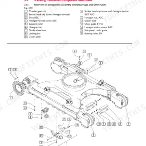
| Undercarriage Disassembly and Assembly | 74-85 | Undercarriage Disassembly and Assembly Procedures, Wheel Removal and Installation, Track Removal and Installation, Sprocket Bearing Plate Removal and Installation |
| Loader Disassembly and Assembly | 86-95 | Loader Disassembly and Assembly Procedures, Lift Cylinder/Tilt Cylinder Removal and Installation, Lift Cylinder/Tilt Cylinder Seal Kit Removal and Installation |
| Quick Attach Disassembly and Assembly | 96-99 | Quick Attach Disassembly and Assembly Procedures, Latch Pin Assembly Removal and Installation, Quick Attach Assembly Removal and Installation, Personal Safety, Machine Preparation |
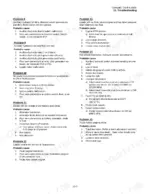
| Troubleshooting | 100-103 | Personal Safety, Machine Preparation (Visual Inspection, Troubleshooting) |
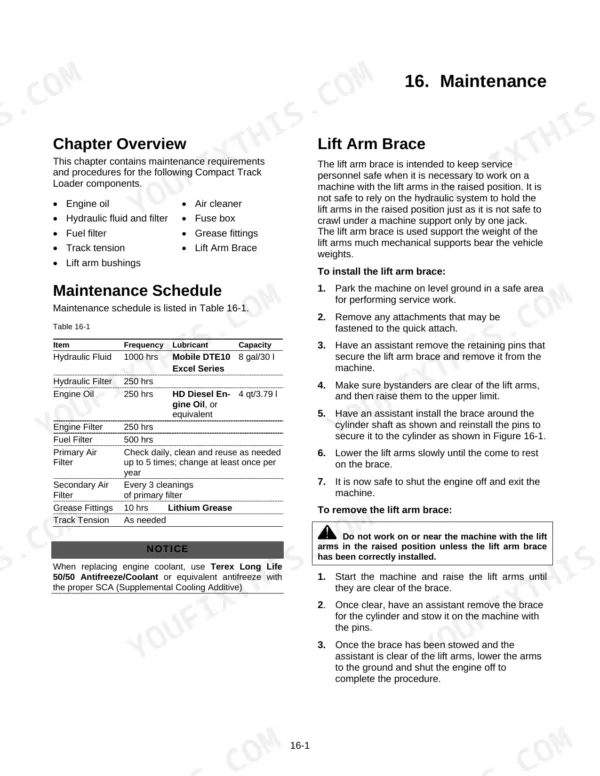
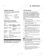
| Maintenance | 104-109 | Maintenance Schedule, Engine Oil (Oil Change Procedures, Specifications), Hydraulic Fluid and Filter (Change Procedures), Fuel Filter (Change Procedures, Fuel Specifications) |
| Hydraulic Pressure Check & Adjustment | 110-116 | Personal Safety, Machine Preparation (Charge Pressure Check, Charge Pressure Adjustment, Drive Pressure Adjustment, Auxiliary Pressure Check & Adjustment) |
Every system also includes chapter overview.
Quick Reference Specifications
| Specification | Value | Page |
|---|---|---|
| Transmission Mounting Bolts | 80 ft-lb (108 Nm) | p. 14 |
| Drive Sprocket Drive Teeth Bolts | 62 ft-lb (84 Nm) | p. 14 |
| Drive Motors Displacement | 19.215 in3/rev (314.9 cc/rev) | p. 14 |
| Drive Pumps Displacement | 1.098 in3/rev (18 cc/rev) | p. 14 |
| Drive Pumps Relief pressure | 3800 psi (26,200 kPa) | p. 14 |
| Engine Displacement | 1.5 liter | p. 14 |
| Gross Horsepower | 33.7 hp | p. 14 |
| Transmission Mounting Bolts Torque | 80 ft-lb | p. 14 |
| Drive Sprocket Drive Teeth Bolts Torque | 62 ft-lb | p. 14 |
| Bogie Wheel Retaining Nuts Torque | 110 ft-lb | p. 14 |
| Drive Sprocket Retaining Bolt Torque (Serial # 00101-05000) | 60 ft-lb | p. 14 |
| Drive Sprocket Retaining Castle Nut Torque (Serial # 05001-Current) | 270 ft-lb | p. 14 |
Terex PT-30 Common Problems This Manual Covers
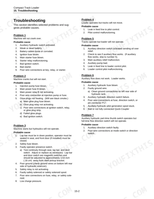
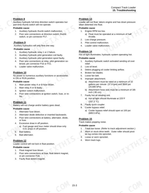
Terex PT-30 compact track loader hydraulics and loader work fine but the tracks will not move
Inspect the feed line for leaks, following the tracks-will-not-move checks on page 101. If the line is tight and dry, check the pilot control for a malfunction. Then verify drive pressure using the Drive Pressure Adjustment procedure starting on page 110; drive pump relief is rated at 3800 psi (26,200 kPa) per page 14.
Manual Section: Loader operates but tracks will not move p. 101Engine starts and idles normally but the hydraulics will not operate at all
Check that the lap bar is fully down, then test the safety fuse and the operator presence switch following page 101. Verify the ground connection next, then test the safety relay and the safety solenoid. A blown fuse or a bad ground is a quicker find than a failed solenoid, so rule those out first.
Manual Section: Machine starts but hydraulics will not operate p. 101Loader lift arms will not float when the loader control is put in float
Verify engine RPM first, following the float troubleshooting on page 102. Next, check charge pressure with the Charge Pressure Check procedure starting on page 110, and adjust it there if it is out. If RPM and charge pressure are both right, inspect the pilot control and then the loader valve.
Manual Section: Loader will not float p. 102Hot oil light comes on and the hydraulic system runs hot while working an attachment
Check hydraulic oil level first; the system holds 8 gal per page 104. Clean debris out of the oil cooler, inspect the fan blades and fan belt, and check the auxiliary hydraulic switch. Following page 102, verify the attachment rating, then check the quick coupler, hot oil sending unit and cooler bypass relief.
Manual Section: Hot oil light illuminates; hydraulic system operating hot p. 102Battery will not charge and the machine keeps going dead between work shifts
Check the alternator fuse first, then test the alternator diode and clean and tighten the wire connections following page 102. Test for excessive draw on the electrical system. If the draw checks out, test the battery itself, and only replace the alternator once the battery and wiring have been ruled out.
Manual Section: Battery will not charge and/or battery goes dead p. 102Track makes a repeated popping noise from the undercarriage while the machine is traveling
Check track tension first, following page 102. Inspect the drive teeth, sprocket and track lugs for wear or damage. If the drive teeth need replacing, torque the drive sprocket drive teeth bolts to 62 ft-lb (84 Nm) dry per page 14; track removal and installation starts on page 74.
Manual Section: Track makes popping noise p. 102Frequently Asked Questions
What are the torque specifications for fasteners on the Terex PT-30?
The manual provides several critical torque specifications. For example, transmission mounting bolts require 80 ft-lb (108 Nm) with Blue Loctite, while drive sprocket drive teeth bolts require 62 ft-lb (84 Nm) dry. Bogie wheel retaining nuts should be torqued to 110 ft-lb (149 Nm) dry, and the drive sprocket retaining castle nut (for serial # 05001-Current) requires 270 ft-lb (366 Nm). p. 14
What are the replacement specifications for the drive motor on a Terex PT-30?
The drive motors are model Rexroth Sauer Danfoss with a displacement of 19.215 in3/rev (314.9 cc/rev). For removal and installation procedures, refer to Chapter 12, page 84. p. 14
How often should I change the hydraulic fluid on a Terex PT-30?
The hydraulic fluid should be changed every 1000 service hours. The capacity for the hydraulic reservoir is 8 gallons (30 liters), and the recommended lubricant is Mobile DTE10 Excel Series. p. 104
How do I bleed the fuel system on a PT-30 with serial number 1358 or higher?
For machines with serial numbers 1358 and higher, locate the bleed screw directly above the fuel injectors and loosen it two full turns. Pump the bulb primer by hand until fuel flows from the bleed screw without any air bubbles, then tighten the bleed screw. p. 72
What is the service limit for the lift arm bushings?
The maximum recommended wear on the lift arm bushings is 50%, which corresponds to a service limit of .063 inches. p. 109
Is this Terex PT-30 manual a download or a disc?
You get a 116-page searchable PDF that downloads instantly after checkout. Open it on your laptop, tablet, or phone, and bring it right to the shop floor.
Can I print this Terex PT-30 manual?
You can. Print the sections you want for your own use and keep the file as your backup.



Reviews
There are no reviews yet.