
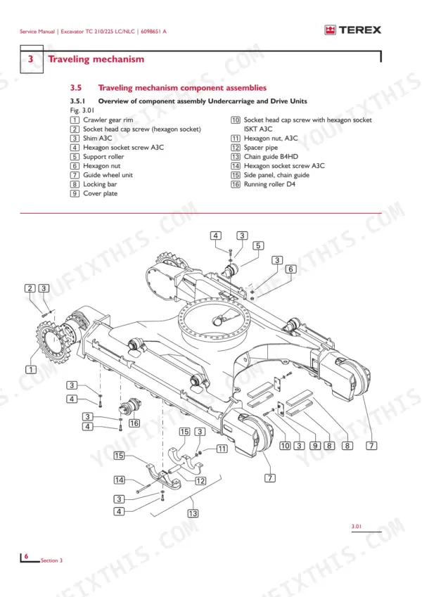
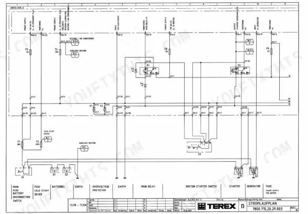
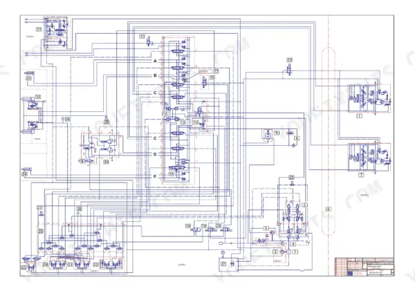
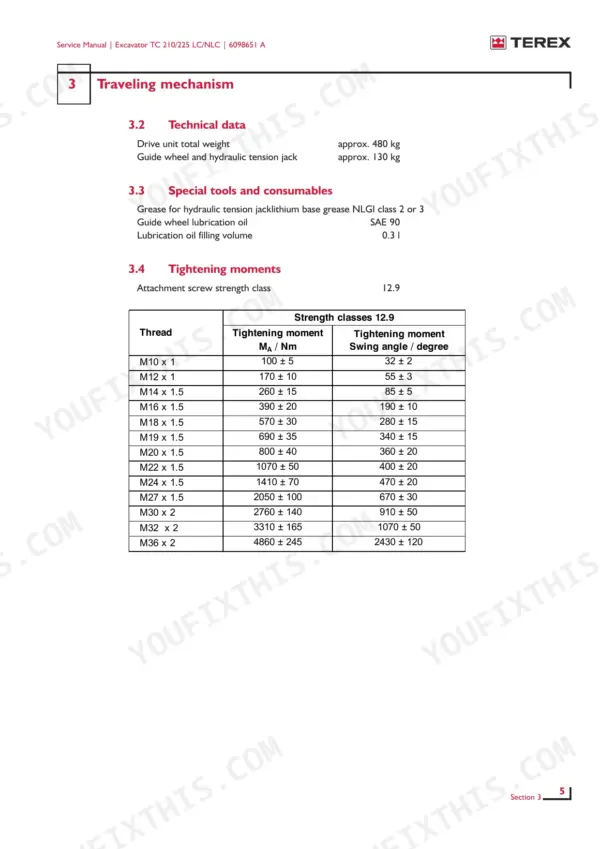
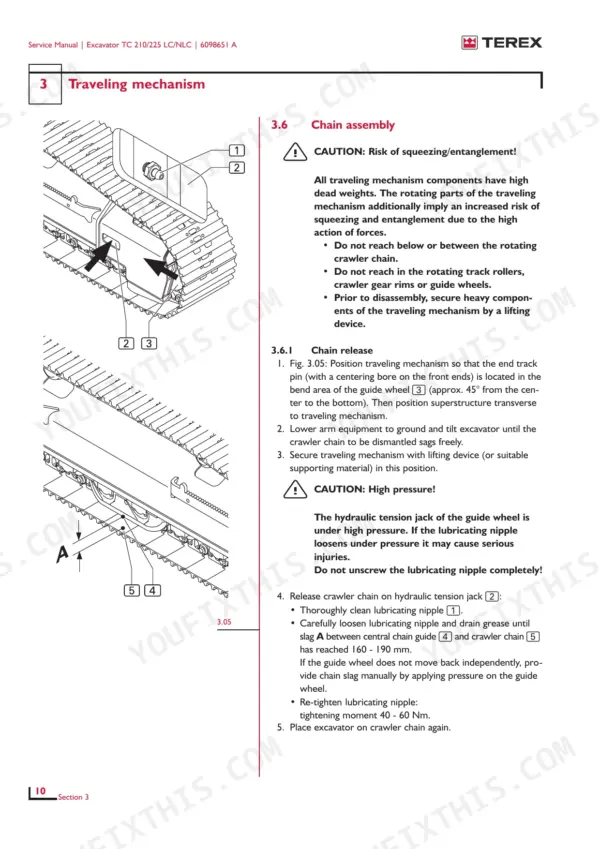
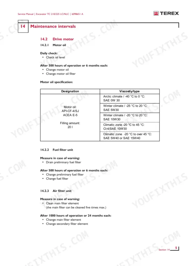
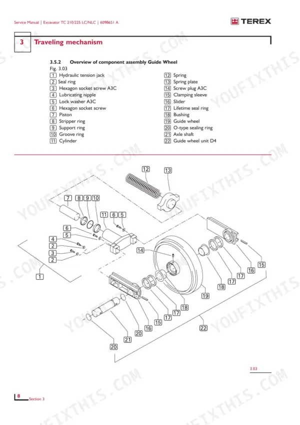
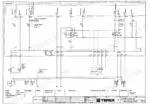
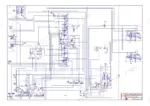
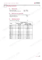
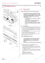
Printed under Terex order number 6098651 A, this 373-page factory service manual covers the TC 210 and TC 225 crawler excavators in four variants, on both LC and NLC undercarriages. Hydraulic diagrams for the shovel, boom, travel, slewing and swan neck jib circuits close out the book next to the wiring diagrams, so your Terex TC 210 LC, TC 210 NLC, TC 225 LC or TC 225 NLC service manual PDF traces oil from pump to cylinder. Teardowns of the main pump, control block, slewing gear and travel motor fill most of the pages, each built around exploded views, and a closing amendment chapter covers what changes on the 225 LC/NLC. Set crawler chain sag to 160 to 190 mm, then tighten M16 x 1.5 threaded connections to 390 ± 20 Nm. Splitting a travel motor from memory is slow going. The bookmarked, text-searchable PDF takes you straight to the right assembly drawing, and your excavator is back on its tracks sooner.
What's Inside This Terex TC 210/225 LC/NLC Manual
| System | Pages | Key Topics |
|---|---|---|
| Safety Instructions / Safety Measures | 5-7 | Warning Signs Within Service Instructions, Signs Attached to Equipment or Mounted-On Devices |
| General Notes on Inspection and Maintenance Work | 8 | Safety Devices, Test Operation, Test Rides |
| Work on the Counterweight | 9-13 | Work on and with Load Suspension Equipment, Dismantling of Excavator Counterweight |
| Work on the Hydraulic System | 14-18 | Hydraulic System Safety and Control Instruments, Hydraulic System Filling Level Control, Hydraulic Fluid Refill, Hydraulic System Pre-Stress Pressure |
| Work on the Air-Conditioning System | 19 | Refrigerant, Cooling Circuit, Refrigerant Container |
| Work on the Drive Motor | 20 | Drive Motor, Protective Gloves, Skin Burns |
| Drive Motor | 21-23 | QSB6.7 Motor Technology, Hydraulic Components, Operation Manual, Maintenance Manual |
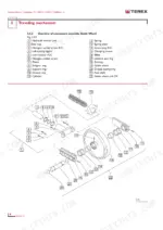
| Traveling Mechanism | 24-45 | Traveling Mechanism Component Assemblies, Chain Assembly |
| Hydraulic System Settings | 46-53 | General Values for Tightening Moments |
| Main Pump / Auxiliary Pumps | 54-103 | Main Pump, Auxiliary Pump Component Assemblies, Driving Gear Component Assemblies, Controller Component Assemblies |
| Control Block | 104-123 | Overview of Control Block Components |
| Slewing Mechanism | 124-166 | Slewing Motor Components, Slewing Gear Component Assemblies |
| Travel Motor / Crawler Gear | 167-220 | Travel Motor Component Assemblies |
| Pilot Control Block | 221-235 | Output Designations, Input Designations |
| Pilot Control Equipment | 236-248 | Travel Pilot Control Unit, Working Tools Pilot Control Unit |
| Arm System – Hydraulic Cylinders | 249-277 | Cylinder Disassembly, Installation of Sealing Parts |
| Hydraulic System Auxiliary Equipment | 278-293 | Rotatory Connection Components |
| Air Conditioning System | 294-315 | Function and Components of the Air Conditioning System, Compressor, Condenser, Fault Diagnosis |
| Maintenance Intervals | 316-329 | Motor Oil, Fuel Filter, Air Filter, Coolant, Hydraulic System, Traveling Gear |
| Instructions for Welding | 330-337 | Repair Preparation |
| Technical Data | 338-342 | Weight and Capacity Data |
| Hydraulic Diagrams | 343-373 | Shovel, Boom, Travel, Slewing Mechanism, Swan Neck Jib |
Quick Reference Specifications
| Specification | Value | Page |
|---|---|---|
| Tightening moment M10 x 1 | 100 ± 5 Nm | p. 28 |
| Tightening moment M12 x 1 | 170 ± 10 Nm | p. 28 |
| Crawler chain slag | 160 - 190 mm | p. 33 |
| Main and secondary air filter element replacement interval | After 1000 hours of operation or 24 months | p. 320 |
| Hydraulic oil filter element replacement interval | After 500 hours of operation or 6 months | p. 322 |
| Preliminary fuel filter replacement interval | After 500 hours of operation or 6 months | p. 320 |
| Fuel filter replacement interval | After 500 hours of operation or 6 months | p. 320 |
| Counterweight weight (TC 210) | 4,580 kg | p. 9 |
| Drive unit total weight (Traveling mechanism) | approx. 480 kg | p. 28 |
| Guide wheel and hydraulic tension jack weight | approx. 130 kg | p. 28 |
| Main pump pressure (Pump 1 & 2) | 340 bar | p. 52 |
| Hydraulic oil tank volume | 216 liters | p. 59 |
Terex TC 210/225 LC/NLC Common Problems This Manual Covers
Terex TC 210 LC main pump pressure reading low at the service port during pressure check
Check main pump pressure at the service port, reading pump 1 and pump 2 against 340 bar as listed on page 52. Run the pilot control pressure check at the same time so you know whether the fault sits in the pump or the pilot side. Keep clear of fittings under load; escaping oil is a burn and fire hazard.
Manual Section: Hydraulic System Settings p. 52Crawler travel motor pressure reading below spec during the hydraulic system settings check
Measure crawler travel motor pressure and compare it against the 350 bar listed on page 53, not the 340 bar pump figure, because the two values differ. If the travel side reads low while pump pressure is correct, move to the travel motor and crawler gear section starting on page 167 before you pull anything apart.
Manual Section: Hydraulic System Settings p. 53Crawler chain sag out of spec with track tension too loose or too tight
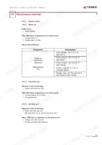
Measure crawler chain sag following the procedure on page 33 and adjust it to 160 to 190 mm. Tension is set through the guide wheel and hydraulic tension jack. When refitting the lubricating nipple, torque it to 40 to 60 Nm. The guide wheel and jack assembly weighs about 130 kg, so rig it properly.
Manual Section: Traveling Mechanism p. 33Air conditioning reduced or no cooling power with loud compressor noise and squeaking V-belt
Inspect the V-belt if it squeaks, then check that the fan actually runs before you blame the compressor. Work through the fault diagnosis for reduced or no cooling power in the air conditioning section starting on page 294. Wear protective clothing when you open the cooling circuit; the refrigerant handling rules are on page 19.
Manual Section: Air Conditioning System p. 294Slewing gear running hot, noisy or leaking during test run after repair
Test the slewing gear with a test run and judge it on three counts: thermal, acoustic and leakage. Check for particle residues before you sign it off. The slewing motor and slewing gear component assemblies are covered in the slewing mechanism section starting on page 124, so strip and inspect them there if the test fails.
Manual Section: Slewing Mechanism p. 124Pilot control pressure wrong at connection lines with visible leakage at the pilot control equipment
Measure pressure at each pilot connection line and compare the readings against the values in the pilot control equipment fault diagnosis. Inspect the lines and fittings for leakage from a safe distance, because this is a high-pressure system. If the readings are off at the source, check the pilot control block, which is covered from page 221.
Manual Section: Pilot control equipment fault diagnosisFrequently Asked Questions
What is the tightening torque for the M10 x 1 thread on the Terex TC 210/225 LC/NLC traveling mechanism?
The tightening torque for an M10 x 1 thread in the traveling mechanism is 100 ± 5 Nm. p. 28
How often should the main and secondary air filter elements be replaced on the Terex TC 210/225 LC/NLC excavator?
The main and secondary air filter elements should be changed every 1000 hours of operation or every 24 months, whichever comes first. p. 320
What is the tightening torque for the piston locking bolt on the Terex TC 210/225 LC/NLC hydraulic cylinders?
The piston locking bolt on the hydraulic cylinders requires a tightening torque of 25 Nm. p. 254
What is the hydraulic oil tank filling capacity on the Terex TC 210/225 LC/NLC excavator?
The hydraulic oil tank has a filling capacity of 216 liters. p. 341
What is the tightening torque for the travel motor crawler gear shaft nut on the Terex TC 210/225 LC/NLC?
The shaft nut on the travel motor crawler gear must be tightened to 3500 Nm. p. 216
Will this Terex TC 210 LC Service Manual download right away?
One searchable PDF covering 373 pages, delivered instantly. No disc, no shipping, no waiting on the post.
Is this Terex TC 210 LC manual print-friendly?
You can. Print the sections you want for your own use and keep the file as your backup.



Reviews
There are no reviews yet.