Main pump, swing motor, travel motor, main control valve: shop manual 023-00089E walks each of those systems end to end across 625 pages, covering eight Terex TXC hydraulic excavators, 140LC-1 through 470LC-1, in a single Terex TXC shop manual PDF. Hydraulic schematics trace the boom, arm, bucket, swing and travel circuits so you can follow oil from pump regulator to spool, while the electrical section maps the monitoring and engine control systems wire by wire. Cylinder work runs from piston nut removal through slipper seal installation, jig included. Fill the TXC 140LC-1 hydraulic reservoir to 89 liters, then verify the coolant temperature sensor reads 1,372 ohms at 41 degrees C. An excavator parked over a pilot circuit fault costs the whole crew its day. Print the pages your job calls for, let them take the grease at the bench, and keep the bookmarked file clean on the laptop.
What's Inside This Manual
| System | Pages | Key Topics |
|---|
| Safety | 13-52 | Track Excavator Safety, General Hazard Information |
| Specifications | 53-74 | General Dimensions, Working Range |
| General Maintenance | 75-102 | General Maintenance Procedures, Cleaning and Inspection |
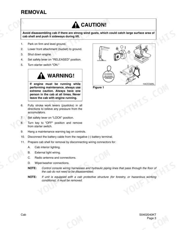
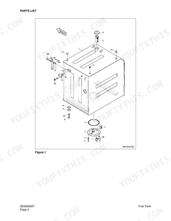
| Upper Structure | 103-158 | Cab, Counterweight, Fuel Tank, Fuel Transfer Pump, Swing Bearing, Swing Reduction Gearbox |
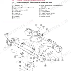
| Lower Structure and Chassis | 159-184 | Track Assembly |
| Engine and Drive Train | 185-222 | Air Conditioner, Drive Coupling |
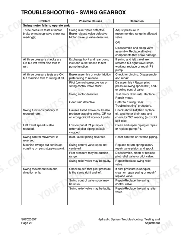
| Hydraulic System Troubleshooting, Testing and Adjustment | 223-256 | Hydraulic Schematic, Boom Operating Circuit, Arm Operating Circuit, Bucket Operating Circuit, Swing Operating Circuit, Travel Operating Circuit |
| Accumulator | 257-262 | Accumulator Description, Specifications, Precharge Pressure, Diaphragm Positions |
| Cylinders | 263-288 | Cylinder Theory of Operation, Disassembly, Assembly, Piston Nut, Slipper Seal Jig |
| Swing Motor | 289-314 | Swing Motor Theory of Operation, Swing Brake Operation, Relief Valve, Disassembly, Reassembly |
| Travel Motor (with Gearbox) | 315-366 | Travel Motor Theory of Operation, Reduction Gearbox Operation, Disassembly, Reassembly, Special Tools |
| Main Pump (with Regulator) | 367-400 | Main Pump Description, Pump Regulator Operation, Overload Protection, Disassembly, Reassembly |
| Main Control Valve | 401-510 | Control Valve Operation, Main Relief Valve, Overload Relief Valve, Arm Load Holding Valve, Plunger Replacement |
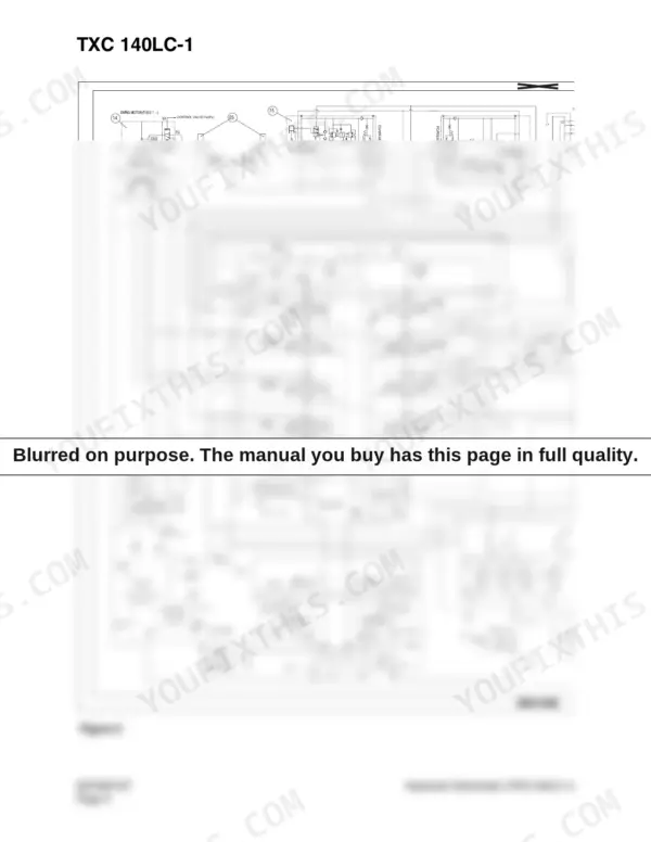
| Hydraulic Schematic (TXC140LC-1) | 511-516 | Hydraulic Schematic, General Notes |
| Electrical System | 517-600 | Monitoring System, Engine Control System |
| Attachments | 601-625 | Boom and Arm, Bucket |
Quick Reference Specifications
| Specification | Value | Page |
|---|
| Socket Bolt Tightening Torque | 10 kg•m | p. 437 |
| Split Flange Bolt Torque (1/2") | 2.1 - 2.5 kg•m | p. 98 |
| Hydraulic Reservoir Capacity | 89 liters | p. 64 |
| Engine Coolant Temperature Sensor Specification (41°C) | 1,372 ohms | p. 536 |
| Socket Bolt Tightening Torque (Main Control Valve) | 10 kg•m | p. 437 |
| Electrical System Voltage | 24 volts | p. 523 |
| Main Relief Pressure (normal operation) | 330 kg/cm² | p. 70 |
| Split Flange Bolt Torque (3/4") | 3.0 - 3.7 kg•m | p. 98 |
| Hydraulic Oil Temperature (Normal Operating Range) | 45° - 55°C | p. 71 |
| Main Relief Pressure (Normal) | 330 kg/cm2 | p. 70 |
| Main Relief Pressure (Pressure Up) | 350 kg/cm2 | p. 70 |
| Fuel Tank Capacity | 230 liters | p. 64 |