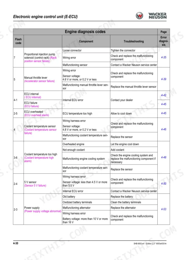
Serial number breaks are where 6003 repairs go sideways, and the Wacker Neuson 6003 service manual pdf settles them: 364 pages of factory documentation for this track excavator (OEM 1000129840) that split coverage by serial range, from instrument panels and fuse boxes to the 4TNV98-VNS and later ZVNS engine builds. Hydraulic schematics trace the pilot oil supply, drive counterbalancing, and boom raise summation circuits, while the engine chapter walks each flash code through its DTC table and a work description, backed by full wiring diagrams. Before you condemn a pump, check the secondary relief: valve position 6 switches at 180 bar, and cylinder-head bolts torque to 103.1 through 112.9 Nm. A misread relief pressure buys you a pump the machine never needed. The text layer answers keyword queries, bookmarks track the chapters, and the file goes wherever your excavator is working.
What's Inside This Manual
| System | Pages | Key Topics |
|---|
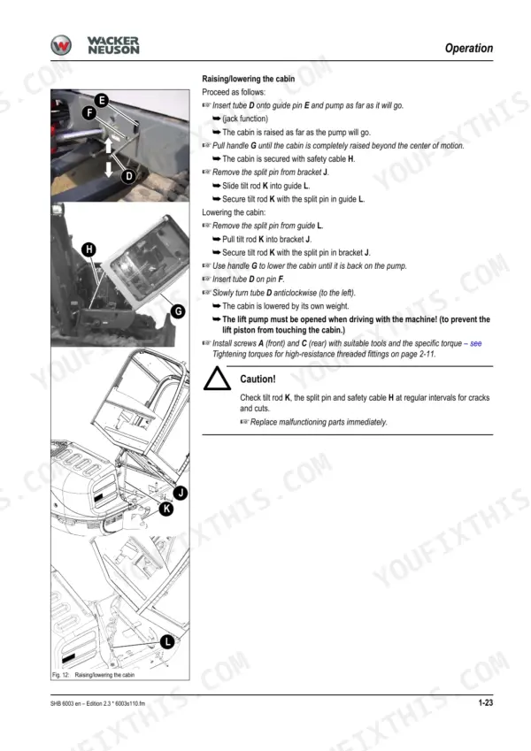
| Operation | 14-39 | Information on This Service Manual, Identification of Warnings and Dangers, Designated Use and Exemption From Liability, Labels, Machine Overview |
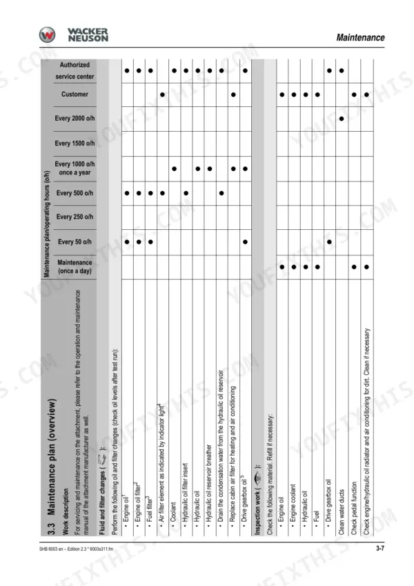
| Maintenance | 54-119 | Fluids and Lubricants (Additional Oil Change and Filter Replacement, Oil Grades for the Hydraulic System, Depending on Temperature) |
| Engine | 120-211 | Engine 4TNV98-Vns (Tier 2), Fuel System, Removing the Cylinder-Head Cover, Checking and Adjusting Valve Clearance (Setting Zero Play of the Valve Bridge, Setting Valve Clearance) |
| Hydraulic Pump and Pilot Oil Supply | 212-216 | Pvd-3B-56P-21G5-4626F Pump, Pump Unit Exploded View, Pilot Oil Supply Unit, Pump Connections |
| Main Valve Block and Diagrams | 217-221 | Main Valve Block Connections, Valve Block Legend, Main Valve Block Diagram, Pump Assignment |
| Drive Counterbalancing and Regeneration | 222-224 | Drive Counterbalancing System, Drive Counterbalancing Diagram, Regeneration Stick Section, Bucket Pre-Tension |
| Boom Raise Summation and Check Valves | 225-227 | Boom Raise Summation, Check Valve Load Retaining Valve, Flow Rate Adjustment of Auxiliary Hydraulics |
| Pilot Valves and Directional Valves | 228-237 | Joystick Pilot Valves, Machine Travel Pilot Valves, Auxiliary Hydraulics Pilot Valves, 4/3 Directional Valve, Sae/Iso Changeover Valve |
| Traveling Drive and Swivel Unit | 238-254 | Trasmital Drive, Kayaba Drive, Swivel Unit, Parking Brake/Multidisk Brake Function, Swivel Joint |
| Breather Filter and Malfunctions | 255-257 | Breather Filter, Hydraulic System Malfunctions, Troubleshooting |
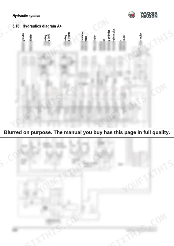
| Hydraulics Diagrams and Options | 258-364 | Hydraulics Diagram A4, Hydraulics Diagram Legend, Options Diagrams, Safe Load Indicator, 3rd Control Circuit, Triple Articulation Boom |
Quick Reference Specifications
| Specification | Value | Page |
|---|
| Cylinder-head bolt | 103.1 – 112.9 Nm (76.04 – 83.27 ft.lbs.) | p. 41 |
| Connecting rod bearing screw | 53.9 – 58.8 Nm (39.75 – 43.37 ft.lbs.) | p. 41 |
| Axial play of the Powertilt | 0.38 mm / 0.015 in | p. 61 |
| Standard play between the shoulder of the sliding block and the contact area of the second support roller of the drive pinion | 20 – 25 mm (1.0 – 1.2") | p. 100 |
| Switch operating point of valve pos. 6 | 180 bar (2611 psi) | p. 239 |
| Engine Output (Tier 2) | 42.5 kW at 2100 rpm | p. 40 |
| Engine Output (Level 3A/Tier 3) | 43.4 kW at 2100 rpm | p. 40 |
| Fuel Tank Capacity | 93 L | p. 41 |
| Hydraulic Reservoir Capacity | 73 L | p. 42 |
| Max. Operating Pressure | 240 bar | p. 42 |
| Battery Capacity | 12 V 88 Ah | p. 43 |
| Engine Oil Capacity (Max) | 10.2 L | p. 54 |