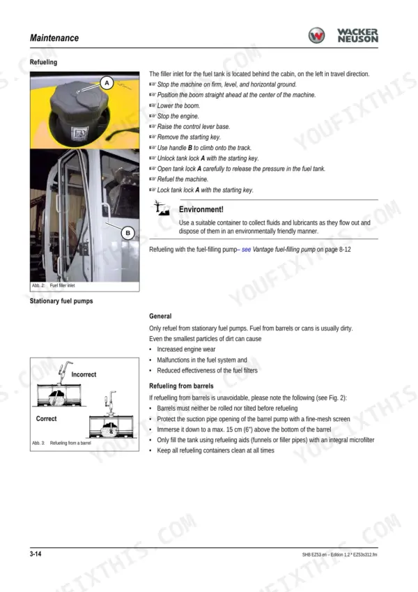
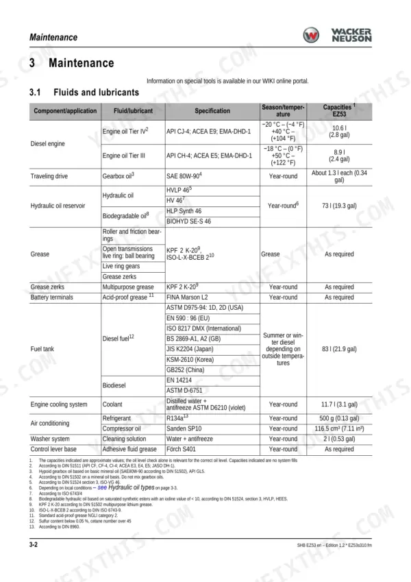
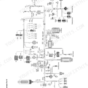
Three wiring harness revisions, split by serial number, make the EZ53's electrical system the trickiest part of this machine to service, and the Wacker Neuson EZ53 service manual PDF sorts all of them across its 270 pages (OEM ID 1000344741). Full electrical and hydraulic diagrams with legends fill the back third of the book, from the main valve block and pilot circuit through the Tier III and Tier IV engine harnesses, matched to your serial number. Malfunction tables for the Perkins engine and hydraulic system pair with the complete maintenance plan, pressure checks for both variable displacement pumps included. Set steel track sag at 20 to 30 mm and torque the track rollers to 275 Nm without second-guessing either figure. A tensioning job stalls fast when the sag spec lives in a book you don't own. Buy it once and this PDF, bookmarked and text-searchable, stays yours for the life of the machine.
What's Inside This Manual
| System | Pages | Key Topics |
|---|
| Operation | 9-20 | Information on This Service Manual, Identification of Warnings and Dangers, Designated Use and Exemption From Liability, Labels, Machine Overview, Engine Compartment |
| Engine | 107-118 | Perkins 404F-22T Tier Iv/404D-22T Tier Iii, Sensors and Electric Components, Turbocharger, Setting the Valve Clearance, Clean the Diesel Particulate Filter, Check the Water Pump |
| Hydraulic System | 119-154 | Hydraulic Pump Pvd-3B-56BCP-21G5-5688A, Pilot Oil Supply Unit, Main Valve Block (Connections, Legend, Diagram, Pressure Limiting Valves), Pump Assignment |
| Electrical System Fundamentals and Components | 155-158 | Ohmic Law, Measuring Equipment, Relays, Alternator, Starter |
| Wiring Harnesses (Tier III and Tier IV, by Serial Number) | 159-173 | Engine Wiring Harness Legend, Wiring Harness Diagrams, Tier IV Up to and From Serial Number Split, Tier III Harness |
| Switch Wiring Harnesses | 174-177 | Switch Wiring Harness Legend, Switch Wiring Harness Diagram |
| Cabin and Armrest Wiring Harnesses | 178-182 | Cabin Roof Wiring Harness, Armrest Wiring Harness |
| Proportional Controls and Telematics | 183-192 | 4th Control Circuit, Telematik Wiring Harness, Fuel-Filling Pump, Boom Working Light, Immobilizer Cable |
| Electrical Diagrams | 193-270 | Hydraulics Diagram Legend, Hydraulics Diagram, Electrical Diagram Legend |
Quick Reference Specifications
| Specification | Value | Page |
|---|
| Track roller | 275 Nm (203 ft.lbs.) | p. 28 |
| Drive pinion | 180 Nm (133 ft.lbs.) | p. 28 |
| Traveling drive | 180 Nm (133 ft.lbs.) | p. 28 |
| Standard play between the shoulder of the sliding block and the contact area of the second support roller of the drive pinion | 20 – 25 mm (0.78 – 0.98 in) | p. 90 |
| Steel track sag | 20 – 30 mm (0.78 – 1.81 in) | p. 91 |
| Switch operating point of valve pos. 6 | 180 bar (2611 psi) | p. 142 |
| Engine Oil Capacity (Tier IV) | 10.6L | p. 38 |
| Engine Oil Capacity (Tier III) | 8.9L | p. 38 |
| Hydraulic Reservoir Capacity | 80L | p. 23 |
| Engine Coolant Capacity | 11.7L | p. 38 |
| Main Pressure Limiting Valve (P1, P2) | 230 bar | p. 23 |
| Main Pressure Limiting Valve (P3) | 215 bar | p. 23 |