A worn center joint or a drive circuit bleeding pressure will park a loader faster than any engine fault. This Weidemann 1150 CX30 repair manual PDF, factory document 1000240977, packs 336 pages of workshop procedures for this articulated wheel loader. Hydraulic and electrical circuit diagrams anchor the back of the book, tracing driving, steering, brake, working and auxiliary hydraulics down to individual plug and contact assignments. Repair procedures claim the largest share by far, carrying you through engine removal, load arm and center joint work, axles, brakes, and cab, each job ending in a verified spec. Set the driving hydraulics to 450 bar working pressure and pull wheel nuts to 150 Nm before the machine rolls again. Guess a pressure wrong and you buy the pump twice. Bookmarked and text-searchable, the file rides along on whatever screen is closest to the loader.
What's Inside This Weidemann 1150 CX30 Repair Manual
| System | Pages | Key Topics |
|---|---|---|
| Safety | 17-36 | |
| Technical Data, Testing Equipment and Special Tools | 37-70 | Technical Data, Filling Quantities, Tightening Torques, Pressure Values, Flow Rates, Safety Stickers, Testing Equipment, Special Tools |
| Inspections, Maintenance Work and Troubleshooting | 71-114 | |
| Complete Vehicle | 115-124 | Helpful Tips, Protective Stickers |
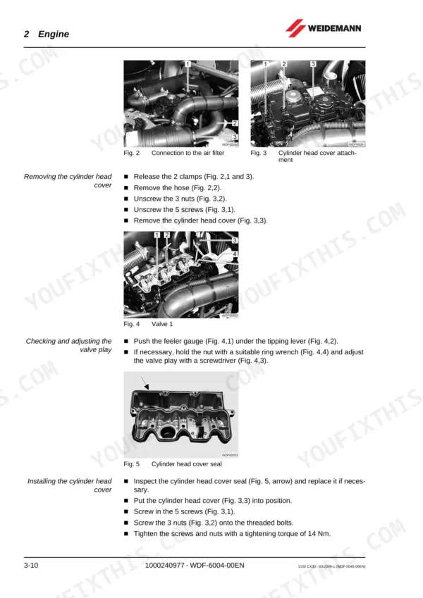
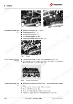
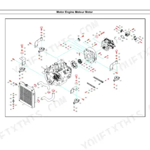
| Engine | 125-154 | Engine Removal, Engine Installation, Rubber Buffers, Radiator, Air Filter System, Fuel System, Exhaust System |
| Hydraulic System | 155-198 | Depressurizing, Hydraulic Cylinder, Driving Hydraulics, Steering Hydraulics, Brake Hydraulics, Working Hydraulics, Auxiliary Hydraulics |
| Drive and Axles | 199-218 | Drive Shaft, Front Axle, Rear Axle, PTO Gear, Axle Shaft Bearing |
| Brake System (Mechanical Section) | 219-226 | Service Brake, Brake Drum, Brake Shoes, Parking Brake, Bowden Cable |
| Vehicle Frame and Load Arm | 227-252 | Front Carriage, Rear Carriage, Center Joint, Step Plate, Load Arm, Tool Attachment |
| Operator's Platform and Cab | 253-260 | Driver's Seat, Seat Belt, ROPS Bar, Steering Column, Steering Wheel |
| Electrical System | 261-286 | Generator, Starter, Switches, Sensors, Relays, Indicator Lamps, Lighting System |
| Circuit Diagrams and Technical Descriptions | 287-322 | Hydraulic Circuit Diagram, Electrical Circuit Diagram, Plug Assignments Contact Assignments, Technical Description |
| Supplier Service Manuals | 323-336 | Engine Workshop Manual, Variable Displ. Pump Repair Instructions, Fixed Displacement Motor Repair Instructions |
Quick Reference Specifications
| Specification | Value | Page |
|---|---|---|
| Wheel nut | 150 Nm | p. 47 |
| Hooked bolt nut | 150 Nm | p. 47 |
| Driving hydraulics working pressure | 450 bar | p. 43 |
| Working hydraulics primary pressure | 205 bar | p. 43 |
| Engine oil with filter capacity | 4 L | p. 45 |
| Generator charging voltage | 14.4 V | p. 43 |
| Generator maximum capacity | 40 A | p. 43 |
| Engine Output | 18.5 kW / 25 HP | p. 43 |
| Engine Capacity | 1,131 cm3 | p. 43 |
| Steering Hydraulics Working Pressure | 175 bar | p. 43 |
| Fuel Tank Capacity | 21 l | p. 45 |
| Hydraulic Fluid Tank Capacity | 8 l | p. 45 |