
The Allied 300 service manual PDF settles which teardown and rebuild sequence applies to your 300, 400 or WD winch, across 84 pages under OEM ID 599009W. Procedures are split by build: the 300 series pinion sprag has its own instructions, separate from the 311 and 400 series, and W and WD input clutches come out differently. A trouble shooting guide works through mechanical and hydraulic checks, and torque tables cover coarse and fine threads, dry or lubricated. Ring gear and pinion tooth contact is charted too. Warm the oil to 180 to 200°F before checking the hydraulic system, then confirm free spool clutch, input clutch and input brake pressures read 240 to 280 psi. Your job may be assembling the free spool clutch pack or installing the pinion brake with its shims. Bookmarks and a searchable text layer get you to that section quickly, down to the correct control valve, R231200 or R242044.
What's Inside This Allied 300, 400, WD Manual
| System | Pages | Key Topics |
|---|---|---|
| Service Manual | 1 | |
| Safety Precautions | 2 | |
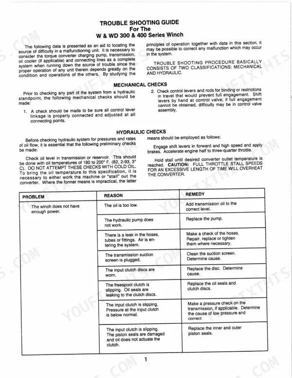
| Trouble Shooting Guide | 5-7 | Mechanical Checks, Hydraulic Checks, Transmission Oil, Hydraulic Pump, Input Clutch Discs, Freespool Clutch |
| Operation of the Winch | 8 | |
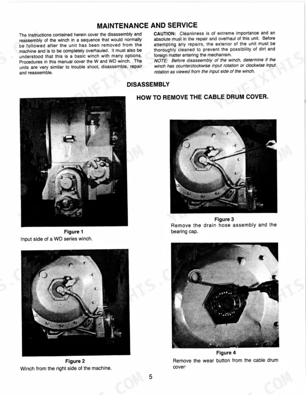
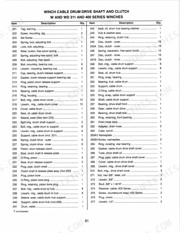
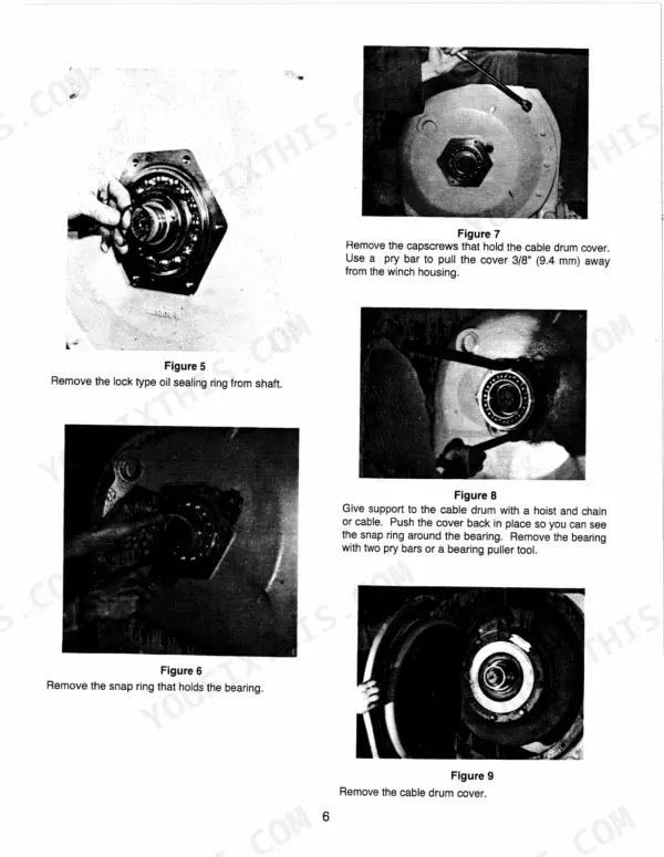
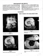
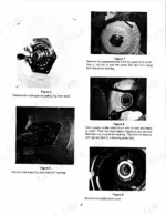
| Maintenance and Service | 9-27 | How to Remove the Drive Gear for the Cable Drum for All Models, Drum Shaft Cover, Bearing Snap Ring, How to Remove the Pinion Shaft and Brake for the W and WD 300 Series Winches, Piston, How to Disassemble the Pinion Sprag for the W and WD 300 Series, How to Remove the Pinion Shaft and Brake for the W and WD 311 and All 400 Series Winches, Disc Hub |
| Cleaning and Inspection | 28 | Gears, Shafts |
| Reassembly of Control Valve | 29-30 | Reassembly of Control Valve R231200, Spacer, Reassembly of Control Valve R242044, Detent Ball, Detent Spring, Valve Spool, Washer, Spring |
| Reassembly of the Input Clutch for All Model Winches | 31-43 | Reassembly of the Input Clutch for All Models, How to Install the Input Clutch Assembly for All W Series Winches, How to Install the Input Clutch and Drop Gear Assembly in All WD Series Winches, Drop Gear, Input Clutch Assembly, O-Rings, Drop Gear Housing, Front Bearing, How to Install the Pinion Shaft for All Model Winches, Inner Bearing, Pinion, Drive Gear |
| How to Install the Cable Drum and Drive Gear | 44-53 | Drum Drive Gear, Shaft, Bearing Assembly, Bearing Locating Ring, Cover, Support Bearing, Oil Seal, Assembly of the Free Spool Clutch, Clutch Disc Hub, Disc Hub Retainer Ring, Steel Discs, Friction Discs, Separator Springs, Clutch Pack, Drum Support |
| Machine Service After Winch Overhaul | 54 | Lubrication |
| Pressures | 55-58 | Free Spool Clutch Pressure, Input Clutch Pressure, Input Brake Pressure, Hydraulic Requirements, Hydraulic Systems, Transmission Fluid, Line Sizes, Sprag Rotation, Input Flange Rotation, Ring Gear Location, Sprag Rotation Direction, Tooth Contact for Ring Gear and Pinion, Tooth Contact Pattern, Backlash, Shim Adjustment, Spiral Bevel and Hypoid Tooth Bearing Contact Chart |
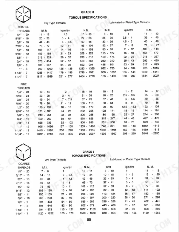
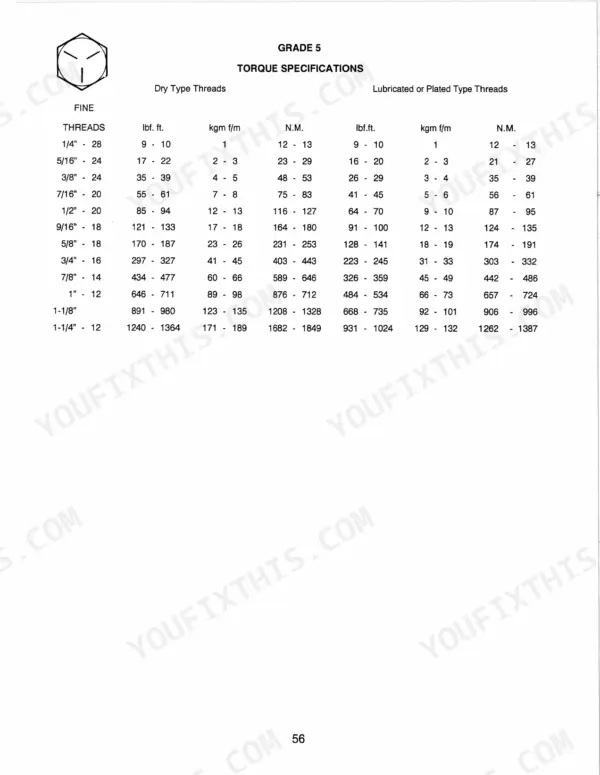
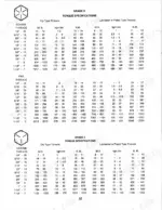
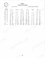
| Torque Specifications | 59-62 | Coarse Threads, Fine Threads, Dry Type Threads, Lubricated or Plated Type Threads |
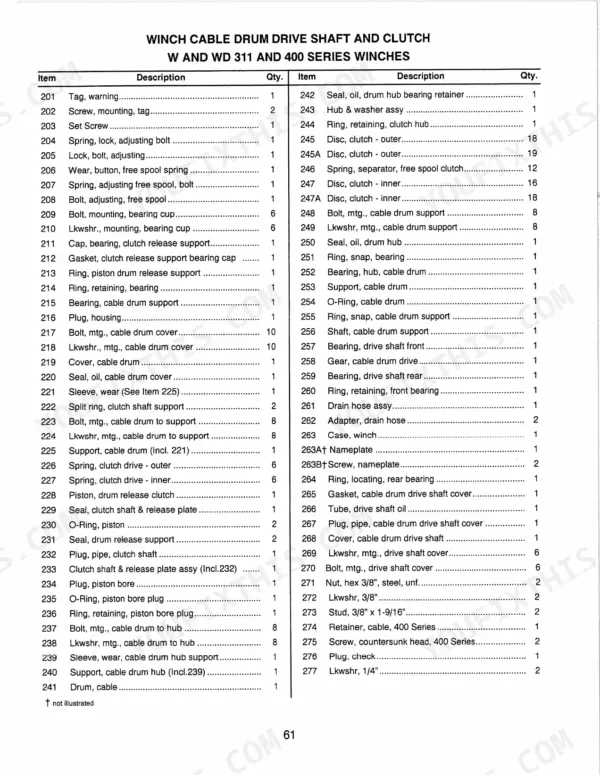
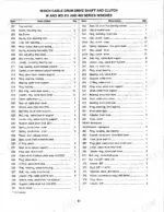
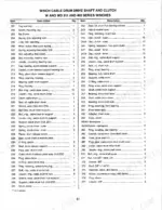
| Parts Identification | 63-84 | Control Valve, Winch Cable Drum Drive Shaft, Clutch, Pinion Shaft, Ring Gear Shaft, Drop Gear Assembly |
Quick Reference Specifications
| Specification | Value | Page |
|---|---|---|
| Oil temperature for checking hydraulic system | 180 to 200° F | p. 5 |
| Free Spool Clutch Pressure | 240-280 psi | p. 55 |
| Input Clutch Pressure (Winch In) | 240-280 psi | p. 55 |
| Input Brake Pressure (Hold) | 240-280 psi | p. 55 |
| Minimum Hydraulic Flow | 3 gallons/minute | p. 56 |
| Winch Functional Supply Line Minimum Size | 3/8 inch ID | p. 55 |
| Control Valve Drain Line Minimum Size | 1/2 inch ID | p. 55 |
| Ring Gear Bolt Torque | 40-60 ft. lbs. | p. 40 |
Allied 300, 400, WD Common Problems This Manual Covers
Allied 300, 400, WD winch input clutch slipping and winch does not have enough power
Check transmission oil level with oil at 180 to 200°F per page 5. Do not attempt these checks with cold oil, and never hold a full throttle stall too long or the converter will overheat. Clean a plugged suction screen, then tighten or replace leaking hoses that let air in. Pressure check the input clutch against 240-280 psi on page 55. Replace damaged piston seals or worn input clutch discs, and find the cause.
Manual Section: Trouble Shooting Guide p. 5Free spool clutch slipping with oil on the discs and winch will not hold a load
Check control valve linkage for damage or wear and verify the control valve to winch hoses are correctly installed. Replace worn or oily free spool clutch discs along with the leaking oil seals; discs go in clean and dry. That clutch holds about 10,000 lbs of force: per page 11, loosen capscrews one turn at a time, and if spring tension remains, stand aside and swap in capscrews twice as long, one at a time.
Manual Section: Trouble Shooting Guide p. 6Pinion sprag or pinion brake suspected when winch will not pull in load and runs slow or uneven
Pressure check the input clutch against 240-280 psi on page 55 with oil at 180 to 200°F, never cold, per page 5. Verify all hoses are correctly installed and check the control valve. Check sprag rotation per page 56 before you connect the input prop shaft; a backwards sprag gets removed, reversed and reinstalled. Inspect the pinion brake piston, guide pins and brake disc, and confirm free spool clutch shim dimensions.
Manual Section: Trouble Shooting Guide p. 6Winch will not operate in free spool position and the clutch discs do not move freely
Check the hose to the free spool clutch for leaks or restrictions, and see that the wear button is free before adjusting the tension handle. Inspect piston shaft seals, separator springs, disc quantity, shim dimensions and clutch pack end plate position, and remove the magnetic field from magnetized steel discs. Before opening the clutch, loosen capscrews one turn at a time per page 11; it holds about 10,000 lbs of force.
Manual Section: Trouble Shooting Guide p. 7Winch control lever keeps popping out and will not remain in the free spool position
Check the detent ball and detent spring in the control valve. Shift the lever by hand at the valve to confirm full engagement. Disassemble valve R231200 following page 22 or valve R242044 following page 23. On R231200, remove the snap ring carefully because the spring behind it is under compression, per page 22. Reassemble following page 25 for R231200 or page 26 for R242044.
Manual Section: Trouble Shooting Guide p. 7Oil pressure low at the winch input clutch while all other pressures read correct
Bring oil to 180 to 200°F before testing; page 5 says never attempt these checks with cold oil. Measure input clutch pressure against 240-280 psi on page 55. Check the input clutch seals for leaks, remove the input clutch supply line and inspect it for restriction, then adjust or repair the control valve or its linkage if it is not functioning correctly.
Manual Section: Trouble Shooting Guide p. 7Frequently Asked Questions
What are the torque specifications for Grade 8 coarse threads on an Allied 300 or 400 series winch?
For Grade 8 coarse threads, the torque specifications vary by bolt size. For example, a 1/2"-13 bolt requires 106-117 lbf. ft. (dry) or 80-88 lbf. ft. (lubricated/plated). A 1"-8 bolt requires 909-1000 lbf. ft. (dry) or 682-750 lbf. ft. (lubricated/plated). p. 59
What is the required hydraulic pressure range for the Allied winch?
The Allied winch requires hydraulic pressures in a range from 240 to 280 p.s.i. Operating below this range will not allow the free spool function to operate correctly, and operating above this range could affect the winch's sealing capacity. p. 56
What is the procedure for checking the preload tension on the ring gear bearing?
Use a cord and scale to find the preload tension. Tie a cord around the gear splines, fasten it to a scale, and pull until the assembly begins to rotate. The scale must show between 19.5 lbs. and 23 lbs. (8.8-10.4 kg), which equals 50-60 lbs./in. preload tension. p. 38
What is the correct procedure for checking the pinion brake shim adjustment?
Install the shims behind the housing and use an inch/lb. torque wrench on the hub nut to measure the torque required to turn the pinion. The second measurement (after tightening the brake housing bolts) must be 15 to 25 lbs.-in. greater than the first measurement. p. 42
What is the required clutch drum spring plate dimension for the free spool clutch?
The distance from the last steel clutch disc to the outer face of the cable drum must be between 6.691 and 6.768 inches (169.9-171.7 mm). If the measurement is outside this range, check the quantity of clutch discs used. p. 48
How will I receive this Allied 300 Service Manual?
Immediate download of the complete 84-page searchable Service Manual. Access it on any device, from a laptop at your desk to a phone in the field.
Can I print a copy of this Allied 300 Service Manual for the shop?
Yes. It prints from any PDF reader, so run off the pages you need for your own repair work.


