
Wrenching on an ASV Rubber Track Loader? This 286-page ASV SR-70, SR-80 Service Manual PDF (OEM #2045-830) covers both machines front to back, from undercarriage to lift arm. Inside: full hydraulic schematics for the charge, auxiliary, and drive circuits, a complete electrical schematic, and step-by-step removal and installation for every pump, motor, and cylinder on your machine. You also get pressure and flow test procedures with troubleshooting for each circuit, plus track removal, tension adjustment, and drive sprocket service. Torque the transmission mounting bolts to 85 ft-lb with blue Loctite, snug the idler wheel retaining nuts to 350 ft-lb dry, and fill the hydraulic system with 12.5 gallons. No more chasing a weak drive circuit with borrowed numbers. Bookmarked chapters and a real text layer let you search any spec and get back under the cab.
What's Inside This ASV SR-70, SR-80 Manual
| System | Pages | Key Topics |
|---|---|---|
| Product Safety | 1-14 | Safety Messages, Protective Equipment, Asbestos Information, Product Identification Number, Machine Labels and Decals |
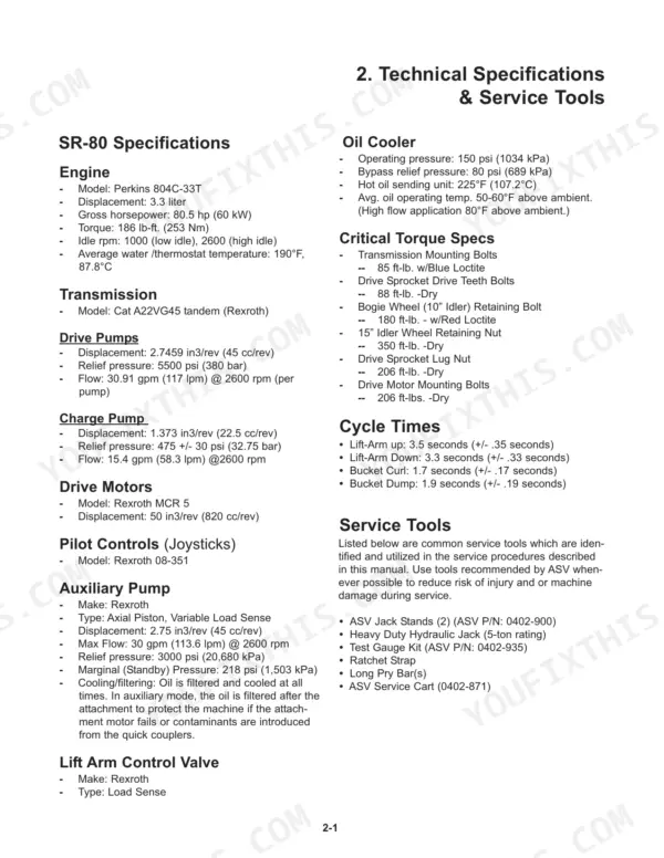
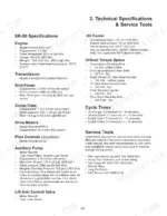
| Technical Specifications & Service Tools | 15-16 | Sr-80 Specifications, Sr-70 Specifications, Critical Torque Specs, Cycle Times, Service Tools |
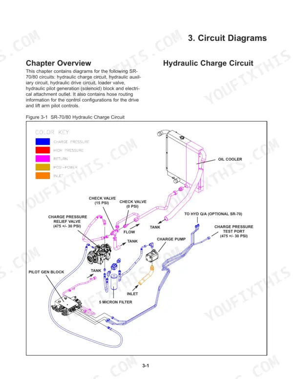
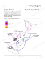
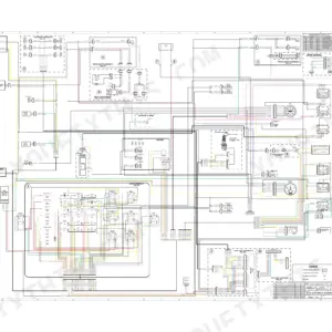
| Circuit Diagrams | 17-24 | Hydraulic Charge Circuit, Hydraulic Auxiliary Circuit, Hydraulic Drive Circuit, Lift Arm Control Valve, Electrical Attachment Outlet |
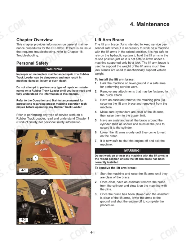
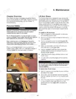
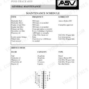
| Maintenance | 25-44 | Lift Arm Brace, Tilt-Up Cab, Jacking Procedure, Grease Fittings, Track Tension, Air Cleaner, Fuel Filter, Accessory Belt Tension |
| Machine Controls and Instrumentation | 45-46 | Machine Controls, Loader Control, Drive Control, Throttle, Instrumentation, Switches |
| Operator Enclosure, Chassis, and Cooling Systems | 47-62 | Operator Enclosure Removal, Fuel Tank Removal, Radiator/Oil Cooler Removal, Fan & Fan Shroud |
| Hydraulic Systems and Components | 63-144 | Hydraulic Reservoir, Lift Arm/Drive Controls, Hydraulic Pumps/Motors, Engine Removal, Undercarriage, Lift Arm Components, Quick Attach, Hydraulic Component Service |
| Posi-Track SR-Series Operator Manual: Introduction and Safety | 145-159 | Machine Introduction, Safety Practices, Warning Decals, PIN Location |
| Controls and Instrument Display | 160-169 | Instrument Display, Gauges and Warning Indicators, Joystick and Switch Functions |
| Operation Techniques | 170-179 | Starting, Driving, Loader Technique, Attachments, Transport and Towing |
| Operator Maintenance | 180-209 | ROPS/FOPS Tilt-Up Access, Air Cleaner, Fluid and Filter Service, Undercarriage Care |
| Standard Torque Guidelines | 210-216 | Inch and Metric Fastener Torque Tables, Thread-Locker Specifications |
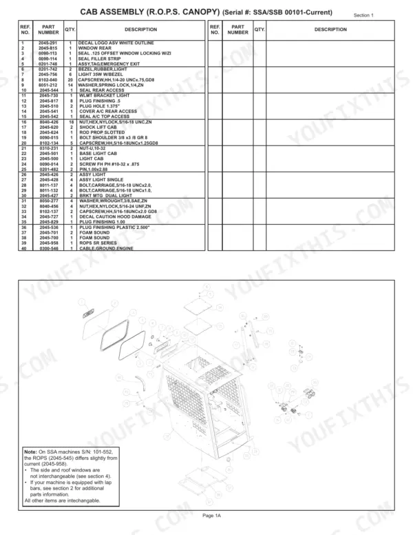
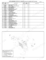
| Master Parts Catalog (Sr-70) | 217-284 | Exploded Views and Part Numbers: Cab Assembly, Chassis, Undercarriage, Quick Attach |
Quick Reference Specifications
| Specification | Value | Page |
|---|---|---|
| All Models | ||
| Transmission Mounting Bolts | 85 ft-lb. | p. 17 |
| Drive Sprocket Drive Teeth Bolts | 88 ft-lb. | p. 17 |
| Hydraulic fluid capacity | 12.5 gal | p. 40 |
| Original rubber tracks warranty period | 24 months or 1,000 operating hours | p. 209 |
| Hydraulic Tank Capacity | 12.25 gal | p. 43 |
| SR-80 | ||
| Engine Gross Horsepower, SR-80 | 80.5 hp | p. 15 |
| Operating Weight with Bucket, SR-80 | 8,972 lb | p. 208 |
| SR-70 | ||
| Engine Gross Horsepower, SR-70 | 71 hp | p. 16 |
| Operating Weight with Bucket, SR-70 | 7,890 lb | p. 208 |
ASV SR-70, SR-80 Common Problems This Manual Covers
ASV SR-70 tracks pop and derail under load, drive sprocket rollers wearing fast
Check track tension per the maintenance procedure on page 25 before condemning parts. Inspect drive sprocket rollers for flat spots and replace worn units, torquing roller bolts to 80 +/- 10 ft-lb as shown on page 210. Retorque drive sprocket retaining bolts to 180 +/- 10 ft-lb while you are in there.
Manual Section: Maintenance p. 25Tracks drive fine but lift arm and bucket controls do not respond
Check the hydraulic reservoir level first; the tank holds 12.25 gallons per page 43, and a low level starves the pilot circuit. Inspect the pilot feed line to the joystick for leaks and loose fittings. Then work through the hydraulics troubleshooting steps starting, comparing against the hydraulic schematic on page 17.
Manual Section: Engine/Machine Troubleshooting p. 137Hydrostatic drive feels weak and jerky, machine loses power pushing into a pile
Drain and replace the hydraulic oil and filter before chasing pump problems; contaminated oil kills these drive systems. The system takes 12.5 gallons per page 40. Run the drive troubleshooting procedures beginning and trace the drive circuit on the hydraulic schematic on page 17 to isolate the weak side.
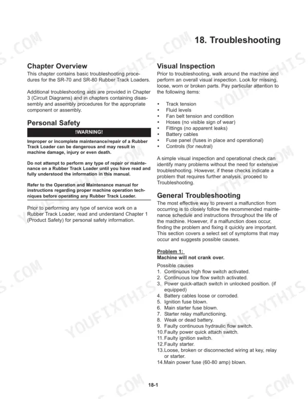
Manual Section: Hydraulic Systems and Components p. 129Machine dead or will not crank, intermittent electrical faults and dashboard warnings
Check battery connections and chassis grounds first; most no-crank complaints on these machines trace back to corroded terminals. Clean and retighten, torquing quarter inch hardware to 9 +/- 2 lb-ft per the standard chart on page 144. Then follow the will-not-crank procedure starting, testing each switch and relay in sequence.
Manual Section: Engine/Machine Troubleshooting p. 17Right-hand loader joystick has excessive play and weeps oil at the boot
Remove the joystick boot and inspect the pilot control valve for worn plungers and leaking seals; a rebuilt assembly beats chasing individual seals. Follow the hydraulic component service procedures in the section starting on page 63. Torque 5/16 inch mounting hardware to 18 +/- 4 lb-ft per the standard chart on page 144.
Manual Section: Hydraulic Systems and Components p. 63Frequently Asked Questions
What are the replacement specifications for drive sprocket rollers?
Drive sprocket rollers should be inspected every 50 hours of operation. They must be replaced if they are found to be cracked or worn to less than 35% of their original thickness, which is 0.088 inches. p. 29
What are the replacement specifications for hydraulic filters?
ASV recommends replacing hydraulic fluid filters every 250 hours of operation. When replacing them, they should always be replaced as a pair. p. 43
What is the correct torque specification for the drive sprocket retaining bolts?
The drive sprocket retaining bolts must be torqued to 180 +/- 10 ft-lbs. p. 210
What is the engine oil capacity for the SR-70 and SR-80 models?
The engine oil capacity for both the SR-70 and SR-80 models is 9 U.S. quarts, which includes the filter. p. 39
What is the correct fan belt deflection for the SR-70/80?
The fan belt should be checked by applying 10 lbs. of force midway between the pulleys. The deflection should measure 3/8 inch when properly tensioned. p. 36
Is this ASV SR-70 manual a download or a disc?
This is a 286-page searchable PDF ready for immediate download. Works on any device, so pull it up on your phone while you're under the hood. No shipping, no waiting.
Am I free to print this ASV SR-70 Service Manual?
Yes. Print the pages or sections you need for your own shop use. Any standard printer works.


Reviews
There are no reviews yet.