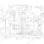
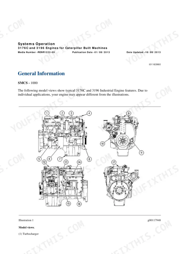
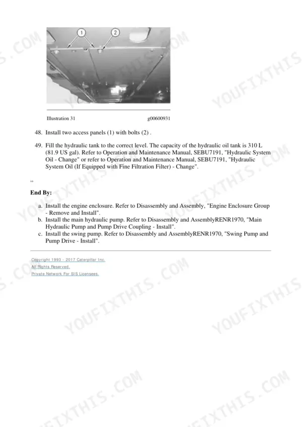
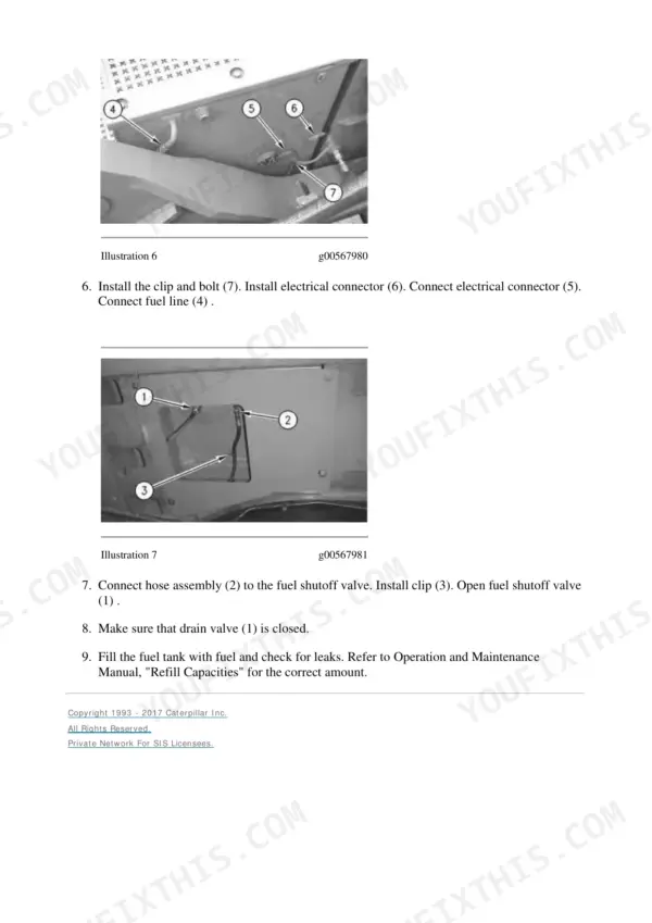
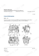
This is the factory Caterpillar SIS repair manual for the 365B and 365B Series II excavators, serial prefixes JMB and DER, running the 3196 engine with electronic unit injectors. All 5,567 pages of it cover everything from valve lash and gear timing through swing drive, final drives, undercarriage and the full hydraulic system with real pressure and flow numbers, not vague ranges. The Hydraulic System section alone runs nearly 2,000 pages, and the book prints new-machine and service-limit values side by side, which is what you actually need when deciding if a pump is worn or a used machine is tired. It closes with the genuine schematics library, including the RENR3765 electrical schematic sheet and hydraulic schematics for standard, attachment, combined function and medium pressure circuits.
What's Inside This Caterpillar 365B Series II Repair Manual
| System | Pages | Key Topics |
|---|---|---|
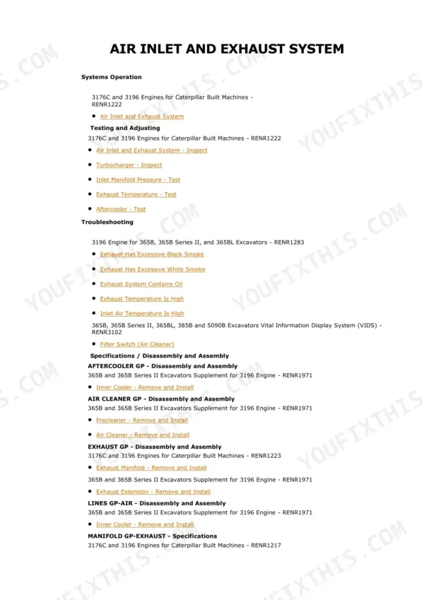
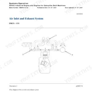
| Air Inlet and Exhaust System | 2-97 | Turbocharger and Aftercooler Tests, Inlet Manifold Pressure, Exhaust Temperature, Black and White Smoke Troubleshooting |
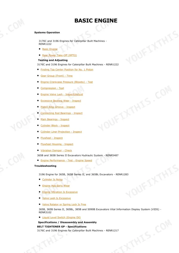
| Basic Engine | 98-508 | 3196 Engine: Rear Power Take-Off, Top Centre Positioning, Gear Timing, Blowby and Compression Tests, Valve Lash, Bearing and Piston-Ring Wear Inspection, Crankshaft and Cylinder Block |
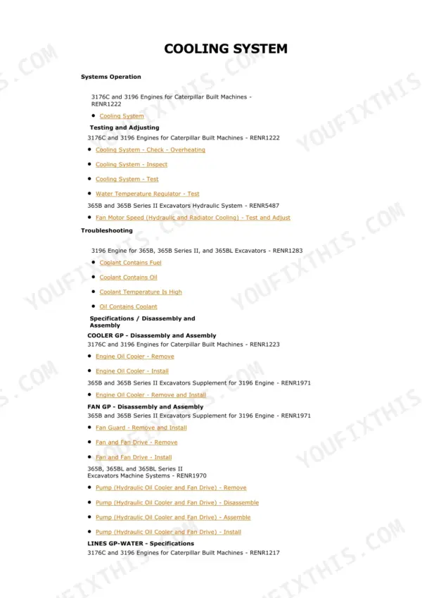
| Cooling System | 509-671 | Overheating Checks, Cooling System Tests, Water Temperature Regulator, Hydraulic and Radiator Fan Motor Speed Test and Adjust, Coolant Contamination |
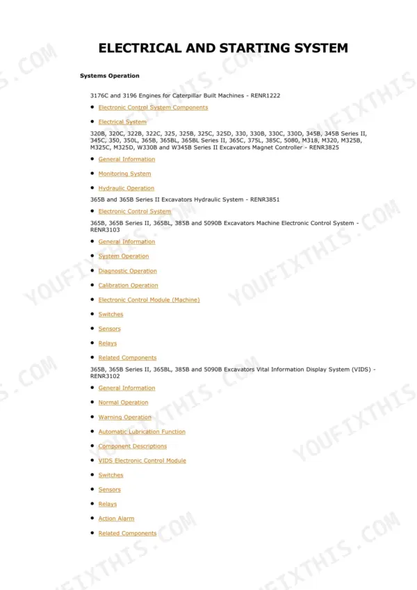
| Electrical and Starting System | 672-1625 | Machine ECM, Monitoring System, Sensors and Switches, Electronic Control System Operation, Diagnostic and Calibration Operation, Harness and Circuit Tests |
| Engine Arrangement | 1626-1712 | Engine Speed Performance Test, Welding Precautions, Component Location, Hard Start, No-Crank, Knock and Shutdown Troubleshooting |
| Frame and Body | 1713-1813 | Swing Drive Removal, Disassembly and Assembly, Counterweight Removal and Lifting Chain, Automatic Lubrication Level Switch, Engine Enclosure |
| Fuel System | 1814-1961 | Electronic Unit Injectors: Adjust and Test, Fuel System Prime, Fuel Pressure and Quality Tests, Air in Fuel, Consumption Troubleshooting |
| Hydraulic System | 1962-3922 | Main and Pilot Hydraulic Systems, Duplicate Load Signal, Pilot Gear Pump, Filters, Relief Valves and Accumulator, Pedal and Joystick Controls, Main Pump, Control Valves, Swing and Travel Motors, Full Testing and Adjusting with Pressure Specifications |
| Implements | 3923-4020 | Boom (Including 7800 Mm and Front Shovel), Boom Bearings and Seals, Bucket Linkage, Stick, Removal and Installation Procedures |
| Lubrication System | 4021-4089 | Oil Pressure and Blowby Tests, Oil Consumption and Temperature Inspection, Oil Contamination Troubleshooting, Oil Pump |
| Machine Arrangement | 4090-4102 | Service Intervals and Heating and Air Conditioning Service Publications |
| Operator Station | 4103-5137 | Cab, Air Conditioning and Heating System with Its Schematic, Refrigerant Compressor, Condenser, Evaporator and Accumulator, Blower and Damper Actuators, Monitor and Controls |
| Power Train | 5138-5247 | Final Drive Removal, Disassembly and Assembly, Duo-Cone Seal Installation, Sprocket, Travel on Level Ground Test |
| Service Equipment and Supplies | 5248-5296 | Cab Pressurisation and Filtration, Refrigerant Manifold Gauge Set Procedures, Required Tools |
| Undercarriage | 5297-5407 | Track Adjuster, Track Roller Frame, Front Idler and Recoil Spring, Rollers and Track Link Removal and Installation |
| Work Tools | 5408-5461 | Combined Function and One-Way and Two-Way Work Tool Hydraulics with Calibration, Medium Pressure System, Bucket Adjuster, Bucket Removal |
| Torque Specifications | 5462-5511 | General Torque Charts for Metric and Inch Fasteners, Fittings and Ground Engaging Tools |
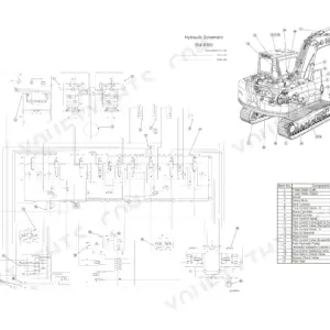
| Schematic | 5512-5567 | Schematics Library: 365B and 365B Series II Excavator Electrical System (RENR3765, 48 by 35 Inch Sheet), Hydraulic Schematics for Standard, Attachment, Combined Function and Medium Pressure Circuits, Magnet Controller Reference Schematic, Fluid Power and Electrical Graphic Symbols |
Quick Reference Specifications
| Specification | Value | Page |
|---|---|---|
| Wear tiers | ||
| Swing pump flow rate | 230 ± 30 L/min (60 ± 8 US gpm) new / 165 L/min (44 US gpm) service limit | p. 2440 |
| Pilot pump flow | 85 ± 5 L/min (22 ± 1 US gpm) new / 70 L/min (18 US gpm) service limit | p. 2447 |
| Right swing, new machine | ||
| Swing time | 6.4 seconds or less | p. 2280 |
| Overswing | 1000 mm (39 inches) or less | p. 2280 |
| Boom cylinder, new machine | ||
| Cylinder drift with empty bucket | 6.0 mm (0.24 inch) or less | p. 2282 |
| New machine | ||
| Boom cylinder operating speed, extension | 4.7 ± 0.5 seconds | p. 2285 |
| Drift reduction valve pressure | 37000 ± 350 kPa (5365 ± 50 psi) | p. 2451 |
| All Models | ||
| Signal relief valve pressure | 32000 ± 490 kPa (4640 ± 72 psi) new / 30040 to 32490 kPa service limit (Boom and stick circuits) / 35000 ± 490 kPa new / 33040 to 35490 kPa service limit (Heavy lift and travel circuits) | p. 2449 |
| Boom and stick cylinders, new | ||
| Cylinder line relief pressure, head end | 37000 ± 490 kPa (5350 ± 72 psi) | p. 2450 |
| Right swing motor, new | ||
| Swing motor relief valve pressure | 34800 ± 1960 kPa (5050 ± 285 psi) | p. 2450 |
| Right travel forward, new | ||
| Travel crossover relief valve pressure | 39200 ± 1470 kPa (5700 ± 215 psi) | p. 2450 |
| Front and rear pumps | ||
| Margin pressure adjusting screw | 1960 ± 100 kPa (285 ± 15 psi) | p. 2450 |
| Adjustment sensitivity 690 kPa (100 psi) per full turn, locknut 16 ± 1 N·m | ||
| Pilot relief valve pressure | 4100 ± 100 kPa (595 ± 15 psi) | p. 2451 |
| Work tool circuit, new | ||
| Hammer relief valve pressure | 16000 kPa (2320 psi) | p. 2457 |
| At -25 °C (-13 °F) | ||
| Pilot accumulator charge pressure | 1490 kPa (216 psi) | p. 2291 |
Caterpillar 365B Series II Common Problems This Manual Covers
Swing loses power and takes too long to reach the truck, or the house coasts too far past the stop point.
Run the swing pump flow test in the Hydraulic System testing and adjusting section: 230 +/- 30 L/min new, 165 L/min service limit. Then check right swing time against 6.4 seconds and overswing against 1000 mm, and verify the swing motor relief at 34800 +/- 1960 kPa before condemning the pump.
Manual Section: Hydraulic System - Testing and Adjusting (pages 1962-3922) p. 2440Pilot controls feel sluggish or dead, joystick response lags, and the machine is hard to operate smoothly.
The Hydraulic System section covers the pilot gear pump with wear tiers, 85 +/- 5 L/min new against a 70 L/min service limit, pilot relief valve adjustment at 4100 +/- 100 kPa, and the pilot accumulator charge check, listed at 1490 kPa at -25 C. Low pilot pressure mimics a dozen bigger failures, so test this circuit first.
Manual Section: Hydraulic System - Pilot System and Accumulator (pages 1962-3922) p. 2447The 3196 engine starts hard, smokes black or white, or falls flat under load in the dig.
Start with the Fuel System section: electronic unit injector adjust and test, fuel system prime, fuel pressure and quality tests, and air-in-fuel troubleshooting. Cross-check with the Air Inlet and Exhaust System procedures for turbocharger tests, inlet manifold pressure and the black and white smoke troubleshooting charts before pulling injectors.
Manual Section: Fuel System (pages 1814-1961) and Air Inlet And Exhaust System (pages 2-97) p. 1814Monitoring system shows a fault, a sensor circuit acts up, or the machine shuts down and no-cranks intermittently.
The Electrical and Starting System section walks through Machine ECM and monitoring system operation, sensor and switch checks, and harness and circuit tests, with diagnostic and calibration procedures. The Engine Arrangement section adds hard start, no-crank, knock and shutdown troubleshooting, and the RENR3765 electrical schematic sheet lets you trace any circuit wire by wire.
Manual Section: Electrical And Starting System (pages 672-1625) p. 672Frequently Asked Questions
My swing is getting slow and weak. Does the manual tell me if the swing pump is actually worn out?
Yes, and with hard numbers. Page 2440 prints the swing pump flow at 230 +/- 30 L/min (60 +/- 8 US gpm) new against a 165 L/min (44 US gpm) service limit. Page 2280 backs it up with performance checks: right swing time of 6.4 seconds or less and overswing of 1000 mm (39 inches) or less on a new machine. Flow-test the pump, time the swing, and you know whether you are buying a pump or just adjusting a relief valve. p. 2440
The boom drifts down when the machine sits. What is the allowable limit and how do I fix it?
Page 2282 gives the printed allowance: 6.0 mm (0.24 inch) or less of boom cylinder drift with an empty bucket on a new machine. If yours is past that, the book walks you through the cylinder line relief valves, head end set at 37000 +/- 490 kPa (5350 +/- 72 psi) for boom and stick, and the drift reduction valve at 37000 +/- 350 kPa (5365 +/- 50 psi) on page 2451. That separates a leaking valve from a bypassing cylinder before you pull anything apart. p. 2282
Does it cover the pressure settings for the main hydraulic system, or just removal and installation?
Full testing and adjusting with the actual settings. Signal relief valves at 32000 +/- 490 kPa (4640 +/- 72 psi) for boom and stick circuits and 35000 +/- 490 kPa for heavy lift and travel, travel crossover reliefs at 39200 +/- 1470 kPa (5700 +/- 215 psi), margin pressure screws at 1960 +/- 100 kPa, and the pilot relief at 4100 +/- 100 kPa with adjustment sensitivity spelled out at 690 kPa (100 psi) per full turn of the screw. Service-limit bands are printed next to the new values so you can set a worn system honestly. p. 2449
The 365B is an electronic machine. Does the manual handle the ECM, sensors and calibration, or do I need dealer software?
The Electrical and Starting System section runs about 950 pages on the Machine ECM, the monitoring system, sensors and switches, electronic control system operation, diagnostic and calibration operation, and harness and circuit tests. The 3196 fuel section covers adjusting and testing the electronic unit injectors. You still need the wiring side, and the book ends with the real 365B and 365B Series II electrical system schematic, media RENR3765, a 48 by 35 inch sheet, plus the fluid power and electrical symbol references to read it. p. 672
I run a hammer and other work tools on this machine. Are the auxiliary circuits and their settings in here?
Yes. The Work Tools section covers combined function, one-way and two-way work tool hydraulics with calibration procedures, the medium pressure system, and bucket adjuster and removal. The hammer relief valve setting is printed at 16000 kPa (2320 psi) on page 2457, which matters because a hammer circuit relief set to the wrong pressure will beat a breaker to death or leave it hitting soft. The schematics section includes the attachment, combined function and medium pressure hydraulic schematics for tracing the circuits. p. 2457