
Factory repair manual for the Caterpillar 315 and 315L track excavators, serial numbers 4YM00001 and up for the 315 and 6YM00001 and up for the 315L. The engine sections cover the 3046 diesel from valve train to crankshaft, plus fuel, cooling, lubrication, air inlet and exhaust, and the starting system. The hydraulic section carries the numbers you actually need on the gauge: 132 liter/min main pump flow, 34 300 kPa (5000 psi) travel relief, 31 400 kPa (4550 psi) implement and swing, with Testing and Adjusting procedures to check and set them on the machine. Undercarriage, final drives with Duo-Cone seals, boom, stick and bucket linkage, and full hydraulic and electrical schematics finish it out.
What's Inside This Caterpillar 315, 315L Repair Manual
| System | Pages | Key Topics |
|---|---|---|
| Air Inlet and Exhaust System | 2-52 | Air Cleaner Group, Turbocharger, Exhaust Manifold, Inlet Manifold, Muffler Group |
| Basic Engine | 53-380 | Valve System Components, Crankshaft, Piston Strokes, Systems Operation, Testing and Adjusting |
| Cooling System | 381-436 | Water Temperature Regulator, Aftercooler Core, Cooling Passages, Testing and Adjusting |
| Electrical and Starting System | 437-1354 | Starting System Components, Troubleshooting, Testing and Adjusting, Specifications / Disassembly and Assembly |
| Engine Arrangement | 1355-1411 | Testing and Adjusting, Specifications / Disassembly and Assembly |
| Frame and Body | 1412-1433 | Counterweight, Hood, Undercarriage Frame Assembly, Swing Gear and Bearing, Swing Bearing |
| Fuel System | 1434-1697 | Fuel Injection Nozzle, Fuel Injection Pump, Fuel Filter, Systems Operation, Testing and Adjusting |
| Hydraulic System | 1698-2321 | Main Pump, Main Relief Valve, Pilot Circuit, Line Relief Valve, Troubleshooting, Testing and Adjusting |
| Implements | 2322-2342 | Boom, Stick, Bucket Linkage Group |
| Lubrication System | 2343-2404 | Engine Oil Pump, Engine Oil Relief Valve, Engine Oil Bypass Valve, Engine Oil Filter Base, Engine Oil Pressure Test, Engine Crankcase Pressure Blowby Test |
| Operator Station | 2405-2713 | Air Conditioning System, Refrigerant Compressor, Heating System, Cab Heater, Seat Assembly, Hydraulic Activation Control Valve |
| Power Train | 2714-2748 | Final Drives, Final Drive Sprockets, Conventional Duo-Cone Seals |
| Schematic | 2749-2782 | 315 and 315 L Excavators Hydraulic System, Caterpillar 315 and 315 L Excavator Electrical System, Fluid Power Graphic Symbols, Electrical Power Graphic Symbols |
| Service Equipment and Supplies | 2783-2810 | Cab Pressurization and Filtration System, Manifold Gauge Set, Engine Oil Filter Base, Fuel Filter Base, Air Cleaner Group, Duo-Cone Seals |
| Torque Specifications | 2811-2860 | Metric Fasteners, Inch Fasteners, Ground Engaging Tool Fasteners, Face Seal Fittings, Flare Fittings, Air Conditioning Fittings |
| Undercarriage | 2861-2914 | Front Idler, Recoil Spring, Track Roller, Carrier Roller, Hydraulic Track Adjusters, Track Assemblies |
| Work Tools | 2915-2926 | Bucket, Bucket Linkage Group |
Quick Reference Specifications
| Specification | Value | Page |
|---|---|---|
| Main pump flow (no load) | 132 liter/min (35 U.S. gpm) | p. 1706 |
| Pilot pump flow (at load) | 17 liter/min (4.5 U.S. gpm) | p. 1706 |
| Main relief valve pressure - travel | 34 300 kPa (5000 psi) | p. 1706 |
| Main relief valve pressure - implement and swing | 31 400 kPa (4550 psi) | p. 1706 |
| Pilot relief valve pressure | 3450 kPa (500 psi) | p. 1707 |
| Line relief valve pressure | 33 300 kPa (4850 psi) | p. 1732 |
| Exhaust manifold bolt torque | 35 ± 5 N·m (26 ± 4 lb ft) | p. 22 |
| Maximum allowable exhaust manifold warpage | 0.20 mm (0.008 inch) | p. 27 |
| Turbocharger end play | 0.057 to 0.103 mm (0.0022 to 0.0041 inch) | p. 42 |
| Turbocharger clamp torque | 4 ± 1 N·m (35 ± 9 lb in) | p. 43 |
| Turbocharger stud nut torque | 44 N·m (33 lb ft) | p. 43 |
Caterpillar 315, 315L Common Problems This Manual Covers
Weak digging force and sluggish swing or travel
Tee a gauge into the circuit and compare against spec: 34 300 kPa (5000 psi) travel, 31 400 kPa (4550 psi) implement and swing, 132 liter/min pump flow. The Hydraulic System Testing and Adjusting section covers the main pump test and main relief valve adjustment step by step.
Manual Section: Hydraulic System - Troubleshooting, Testing and Adjusting p. 1706Track loosens repeatedly or gets thrown in turns
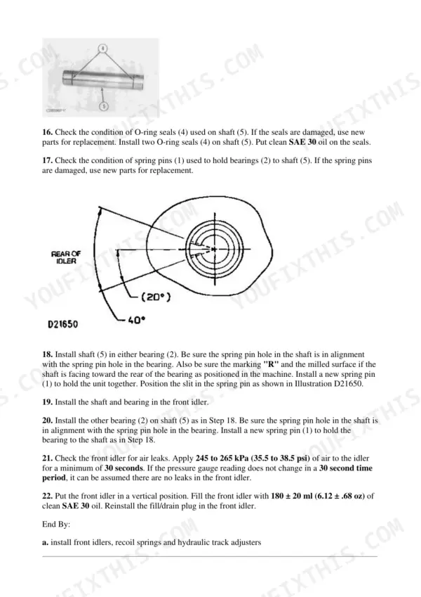
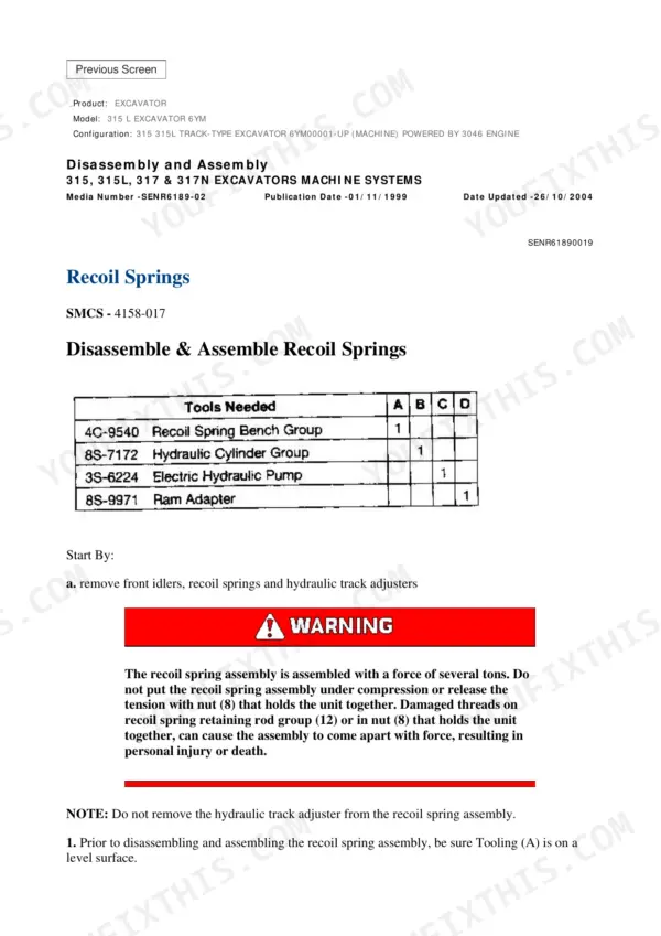
Usually a track adjuster losing grease pressure or a tired recoil spring, sometimes a worn front idler letting the chain wander. The Undercarriage section covers the hydraulic track adjusters, recoil spring service, front idler, and track assembly procedures so you fix the cause instead of just re-tensioning every week.
Manual Section: Undercarriage p. 2861Engine runs hot under load
Start with the water temperature regulator test in the Cooling System Testing and Adjusting section before condemning the pump or radiator. The section also covers the aftercooler core and cooling passages, so you can work through the circuit in order instead of throwing parts at the temperature gauge.
Manual Section: Cooling System - Testing and Adjusting p. 381Low or dropping engine oil pressure
Run the Engine Oil Pressure Test in the Lubrication System section to get a real number before tearing anything down. The section then covers the engine oil pump, oil relief valve, bypass valve, and filter base, which lets you isolate a lazy relief valve from a genuinely worn pump.
Manual Section: Lubrication System p. 2343Frequently Asked Questions
My machine feels weak and slow. Does this manual give the actual hydraulic pressure specs, or just theory?
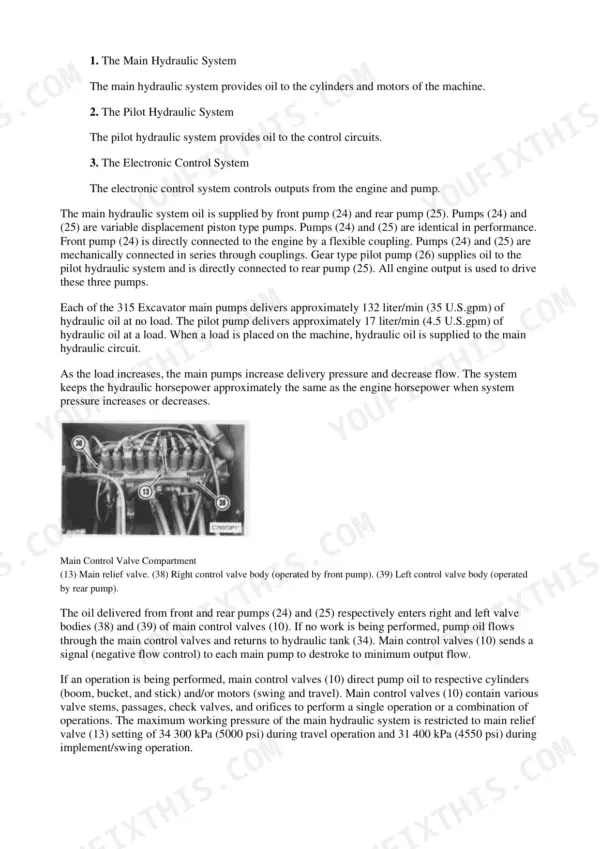
Real numbers, and the procedures to check them. Main relief is 34 300 kPa (5000 psi) for travel and 31 400 kPa (4550 psi) for implement and swing, line reliefs at 33 300 kPa (4850 psi), pilot relief at 3450 kPa (500 psi), main pump flow 132 liter/min at no load. The Hydraulic System Testing and Adjusting section walks you through where to tee in a gauge and how to adjust each valve. p. 1706
Which engine does this cover, and does it include a rebuild level of detail?
The Caterpillar 3046 diesel, per this manual's own spec block. The Basic Engine section covers valve system components, crankshaft, and piston strokes, with Systems Operation and Testing and Adjusting, and the fuel section covers the injection pump and nozzles. It is enough to diagnose, set, and repair the engine, not just top it off and hope. p. 53
Do I need a laptop or diagnostic scanner to use this manual on my 315?
No. These are hydraulic/mechanical machines. Everything in here is done with a pressure gauge, a multimeter, and hand tools. The Electrical and Starting System section troubleshoots with continuity and voltage checks, not trouble codes, because there are no electronic codes on this generation to pull. p. 437
Are wiring and hydraulic schematics actually included, or do I have to buy them separately?
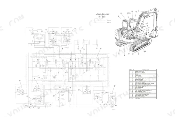
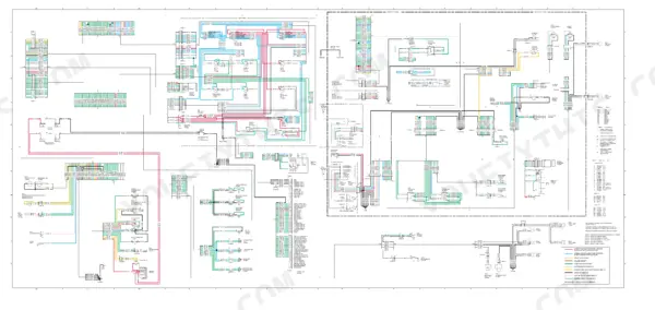
Included. Hydraulic Schematic 104-9165 covers both the 315 and 315L, there is a separate schematic sheet marked specifically for the 315, and the electrical system schematic for both machines is in the Schematic section. Handy when you are chasing a pilot circuit problem or a starting circuit fault. p. 2751
Is the undercarriage covered? Mine eats rollers and the track keeps loosening.
Yes. The Undercarriage section covers the front idler, recoil spring, track and carrier rollers, hydraulic track adjusters, and complete track assemblies. Final drives and sprockets are in Power Train, including the conventional Duo-Cone seals that stop the oil leaks that kill final drives. p. 2861

Reviews
There are no reviews yet.