
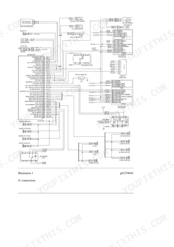
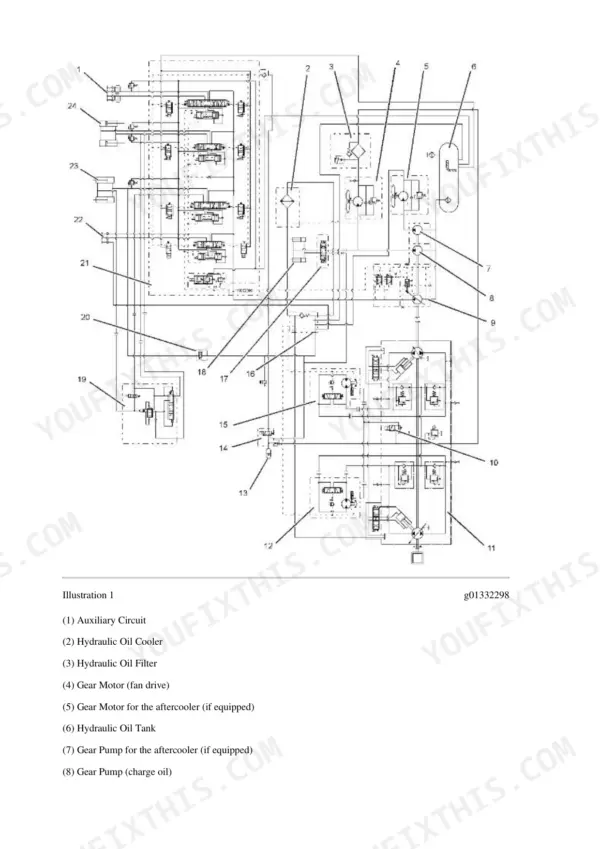
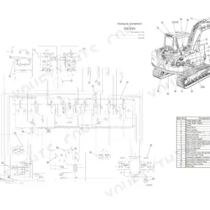
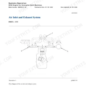
This is the factory Caterpillar service set for the 279C Compact Track Loader, serial prefix MBT00001-UP, with the 3044C engine. You get two downloads: the 2886-page repair book and a separate schematics zip for chasing wires and hydraulic lines. Inside the book: full disassembly and assembly for the hydrostatic piston pumps and motors, the work tool piston pump, tilt and lift cylinders, the 3044C top to bottom (head, pistons, crank, injection pump), plus undercarriage work - idlers, recoil springs, rollers, tracks. Testing and adjusting sections give real numbers: main relief at 23000 kPa, lift pressure at 24500 kPa, charge pressure specs, flow tests. Torque charts, ECM troubleshooting, and the cab air conditioning system are all in here too.
What's Inside This Caterpillar 279C Repair Manual
| System | Pages | Key Topics |
|---|---|---|
| Air Inlet and Exhaust System | 1-47 | Turbocharger, Exhaust Manifold, Air Cleaner, Inlet Manifold, Muffler, Exhaust Temperature |
| Basic Engine | 48-372 | Cylinder Head, Pistons and Connecting Rods, Crankshaft, Balancer, Rocker Shaft, Connecting Rod Bearings, Bearing Clearance, Flywheel |
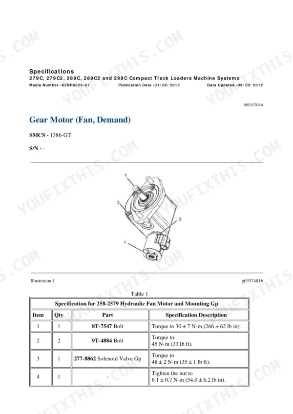
| Cooling System | 373-471 | Water Pump, Water Temperature Regulator, Engine Oil Cooler, Radiator and Hydraulic Oil Cooler, Gear Motor (Fan, Demand) |
| Electrical and Starting System | 472-952 | Electronic Control Module (ECM), Alternator, Glow Plugs, Electric Starting Motor, Wiring Harness (Open Circuit), Wiring Harness (Short Circuit), Electrical Connector |
| Engine Arrangement | 953-1019 | Engine Design, Engine Performance, Testing and Adjusting Procedures |
| Frame and Body | 1020-1033 | Machine Frame and Mounting, Engine Enclosure, Lift Arm Cylinder and Mounting |
| Fuel System | 1034-1142 | Fuel Injection Pump, Fuel Injector, Fuel Injection Nozzle, Fuel Injection Lines, Fuel Priming Pump and Primary Filter (Water Separator), Governor Control, Air in Fuel |
| Hydraulic System: Systems Operation, Testing and Adjusting | 1143-1365 | Work Tool Hydraulic System, Control Valve (Work Tool), Piston Pump (Work Tool), Gear Pump, Electrohydraulic System, Gear Motor (Fan), Operational Checks, Visual Inspection |
| Hydraulic System: Troubleshooting, Specifications, Disassembly and Assembly | 1366-1786 | Piston Pump, Gear Pump (Charge), Tilt Cylinder, Control Manifold (Quick Coupler), Control Manifold and Solenoid (Work Tool Positioner), Accumulator Manifold, System Pressure |
| Implements | 1787-1805 | Lift Arms, Bearings and Mounting |
| Lubrication System | 1806-1850 | Engine Oil Pump, Engine Oil Relief Valve, Engine Oil Bypass Valve, Crankcase Breather, Engine Crankcase Pressure (Blowby), Excessive Engine Oil Consumption |
| Machine Arrangement | 1851-1868 | Service Intervals, Symptom Troubleshooting, Heating and Air Conditioning Service Publications |
| Operator Station | 1869-2390 | Electrohydraulic Control (Joystick), Air Conditioner and Heater, Refrigerant Compressor, Refrigerant Condenser, Refrigerant Receiver-Dryer, Refrigerant Expansion Valve |
| Power Train | 2391-2725 | Piston Pump (Hydrostatic), Piston Motor (Hydrostatic), Hydrostatic System Troubleshooting, Pump Mounting, System Pressure, Operational Checks |
| Service Equipment and Supplies | 2726-2742 | Required Tools, Manifold Gauge Set (Refrigerant), Cab Pressurization and Filtration System, Fuel Priming Pump and Primary Filter (Water Separator) |
| Torque Specifications | 2743-2792 | Metric (ISO) Fasteners, English (SAE) Fasteners, Ground Engaging Tool (G.E.T.) Fasteners, Straight Thread O-Ring Fittings, Hose Clamps, Bulkhead Nuts |
| Undercarriage | 2793-2877 | Idler, Recoil Spring and Track Adjuster, Track Roller, Sprocket, Axle (Front), Axle (Rear), Track |
| Work Tools | 2878-2886 | Bucket, Work Tool Mounting, Quick Coupler |
Quick Reference Specifications
| Specification | Value | Page |
|---|---|---|
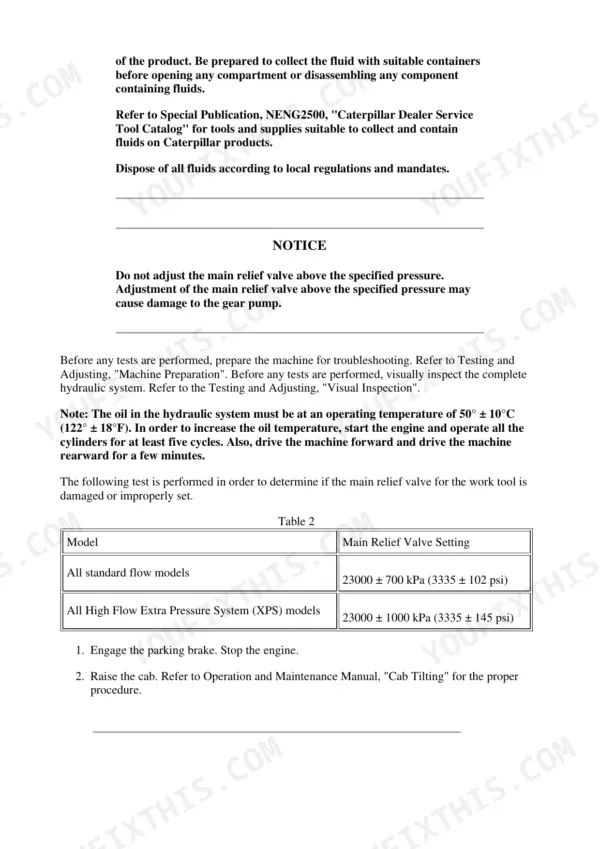
| Main relief valve - all standard flow models | 23000 ± 700 kPa (3335 ± 102 psi) | p. 1288 |
| Main relief valve - High Flow XPS models | 23000 ± 1000 kPa (3335 ± 145 psi) | p. 1288 |
| Lift pressure | 24500 ± 700 kPa (3553 ± 102 psi) | p. 1299 |
| Rack back pressure | 27600 ± 700 kPa (4003 ± 102 psi) | p. 1300 |
| Tilt pressure | 24500 ± 700 kPa (3553 ± 102 psi) | p. 1300 |
| Auxiliary pressure - High Flow XPS | 31000 ± 700 kPa (4496 ± 102 psi) | p. 1300 |
| Pilot accumulator precharge | 900 ± 100 kPa (130 ± 15 psi) | p. 1303 |
| Pilot pressure | 3500 ± 200 kPa (500 ± 30 psi) | p. 1307 |
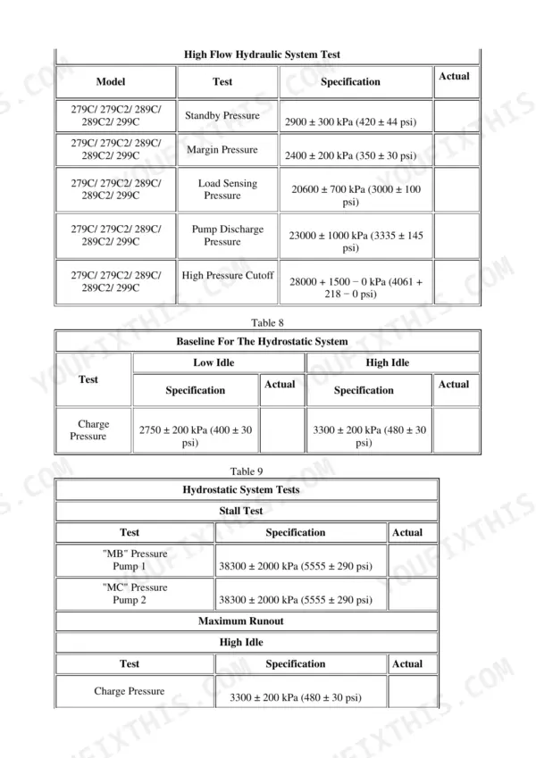
| Charge pressure at low idle | 2750 ± 200 kPa (400 ± 30 psi) | p. 1352 |
| Charge pressure at high idle | 3300 ± 200 kPa (480 ± 30 psi) | p. 1352 |
| Hydrostatic pump pressure at ports MB and MC | 38300 ± 2000 kPa (5555 ± 290 psi) | p. 1352 |
| High pressure cutoff | 28000 + 1500 - 0 kPa (4060 + 218 - 0 psi) | p. 1348 |
| Standby pressure | 2900 ± 300 kPa (420 ± 44 psi) | p. 1341 |
| Load sensing pressure | 20600 ± 700 kPa (3000 ± 100 psi) | p. 1344 |
| Charge pump minimum flow | 36.8 L/min (9.72 US gpm) | p. 1327 |
| Work tool pump minimum flow | 54.3 L/min (14.34 US gpm) | p. 1333 |
| High Flow XPS auxiliary circuit flow | 121 ± 5 L/min (32 ± 1.3 US gpm) | p. 1335 |
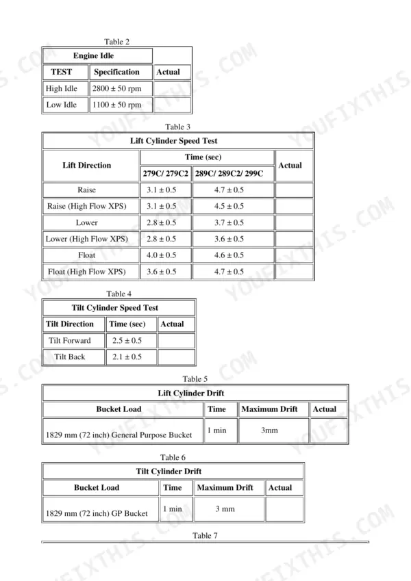
| Lift cylinder raise speed | 3.1 ± 0.5 sec | p. 1351 |
| Lift cylinder maximum drift, 1829 mm bucket in 1 min | 3 mm | p. 1351 |
| Engine high idle / low idle | 2800 ± 50 rpm / 1100 ± 50 rpm | p. 1351 |
Caterpillar 279C Common Problems This Manual Covers
One drive side weak or dead, machine pulls to one side or will not climb a trailer ramp
Start with the charge circuit before condemning a pump. The manual's hydrostatic troubleshooting procedure has you verify charge pressure (2750 ± 200 kPa low idle, 3300 ± 200 kPa high idle) and pump pressure at ports MB and MC against the 38300 kPa spec, then walks through piston pump and piston motor teardown if pressures confirm internal wear.
Manual Section: Power Train - Hydrostatic System Troubleshooting p. 2443Hard starting cold, white smoke, or engine dies and restarts like it is starving for fuel
The Fuel System section covers the air-in-fuel diagnostic, fuel priming pump and primary filter with water separator service, injection nozzle testing, and injection pump removal on the 3044C. Cold-start complaints also send you to the glow plug checks in the Electrical and Starting System section, since dead glow plugs mimic fuel trouble in cold weather.
Manual Section: Fuel System p. 1034Lift arms drift down under load or bucket will not hold tilt position
Run the drift test from the testing section: 3 mm maximum drop in one minute with a 1829 mm bucket. Then verify lift and tilt circuit pressures at 24500 ± 700 kPa. Failed test leads you to tilt cylinder and lift cylinder disassembly, resealing, and the control valve procedures in the hydraulic disassembly section.
Manual Section: Hydraulic System - Troubleshooting, Specifications, Disassembly and Assembly p. 1351Attachments run slow or High Flow tools stall under load
The book gives flow and pressure benchmarks to test against: work tool pump minimum flow of 54.3 L/min, main relief at 23000 ± 700 kPa, and 121 ± 5 L/min on the High Flow XPS auxiliary circuit. Operational checks walk through the work tool control valve, piston pump, and electrohydraulic system so you can isolate a tired pump from a stuck relief valve.
Manual Section: Hydraulic System - Systems Operation, Testing and Adjusting p. 1335Frequently Asked Questions
My 279C creeps weak on one side and drive feels lazy when the oil warms up. Does this manual actually walk through diagnosing the hydrostatic system?
Yes, and this is where the book earns its money. The Power Train section has hydrostatic system troubleshooting with the actual test procedure: hook gauges to ports MB and MC and check for 38300 ± 2000 kPa (5555 psi), then verify charge pressure at 2750 ± 200 kPa at low idle and 3300 ± 200 kPa at high idle. Low charge pressure when hot is the classic cause of one-side weakness, and the manual tells you where to tap in and what a healthy pump reads before you spend money on a rebuild. p. 2443
The lift arms slowly sink with a loaded bucket. How do I know if it is the cylinders or the control valve?
The manual gives you a pass/fail number so you stop guessing: with a 1829 mm bucket, maximum lift cylinder drift is 3 mm in one minute. The Hydraulic System testing section walks through checking lift circuit pressure (24500 ± 700 kPa on the 279C) and isolating cylinder piston seals from valve leakage. The Disassembly and Assembly section then covers cylinder teardown and resealing if the cylinders fail the test. p. 1351
Does this cover the High Flow XPS version, or just standard flow machines?
Both. The tables split standard flow and High Flow XPS wherever the numbers differ: main relief is 23000 ± 700 kPa on standard flow and 23000 ± 1000 kPa on XPS, auxiliary pressure on XPS runs 31000 ± 700 kPa, and the XPS auxiliary circuit should flow 121 ± 5 L/min. One caution from someone who has been burned: the tables also print a second column for the 289C/299C with different numbers, so make sure you read the 279C column. p. 473
The machine has an ECM and a monitor. Can I pull diagnostic codes with this manual, or do I need dealer software?
The 279C has a Machine ECM, and the Electrical and Starting System section covers ECM troubleshooting, wiring harness open circuit and short circuit checks, and connector inspection procedures. You can do a lot with a multimeter and the schematics zip. That said, full code reading and configuration goes through Cat Electronic Technician (Cat ET), which is dealer-level software the manual references but does not replace. The wiring diagnostics alone solve most no-start and sensor problems without it. p. 1355
Are the electrical and hydraulic schematics actually included, or is that another purchase?
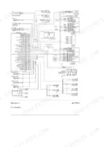
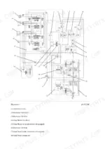
Included. You download two files: the 2886-page repair manual and a separate schematics zip with the electrical and hydraulic sheets plus the Cat symbol legends. Having the schematics as standalone files matters in practice - you can print the wiring diagram or keep it open on a tablet next to the machine while the repair book stays open on the bench procedure. p. 1
![Caterpillar 311 repair manual - Electrical & Starting System, [Elec #12-1] Wiper System Problem](https://youfixthis.com/wp-content/uploads/2019/12/caterpillar-311-repair-manual-9lj00262-up-excavator-page-575-150x150.webp)

Reviews
There are no reviews yet.