
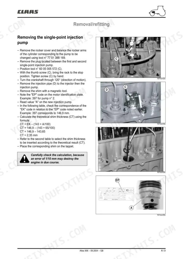
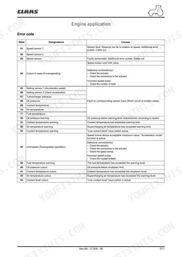
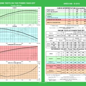
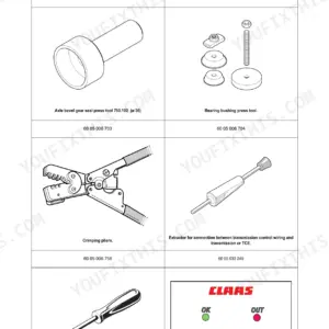
All 731 pages of this Claas Atles 926, Atles 936, Atles 906 repair manual PDF cover one tractor family, from the 7,151 cm³ Tier II engine to the Full Powershift gearbox and pneumatic braking system. You get factory wiring diagrams with connector grids and harness paths, closed centre hydraulic schematics, WIN Metadiag fault code procedures, and page after page of tightening torques. Inside: gearbox reconditioning, rear and front axle rebuilds, brake and park lock service, TCE 25 electronic linkage calibration, cab lift, and air conditioning work. Set new injector opening pressure at 250 ± 12 bar and check clutch feed pressure against the 17 bar spec before you blame the solenoids. No more chasing harness faults with a test light and a prayer. Bookmarked by system; pull it up on your phone in the shop and search any spec by keyword.
What's Inside This Claas 926-936 Repair Manual
| System | Pages | Key Topics |
|---|---|---|
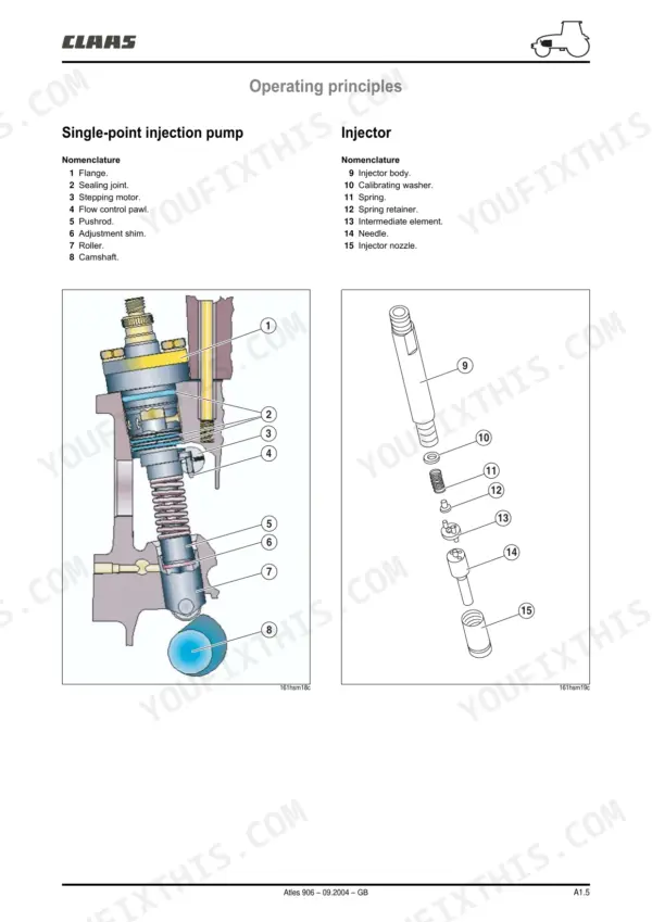
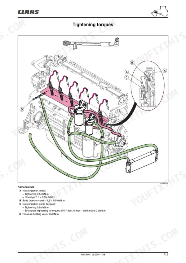
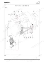
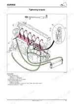
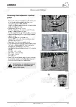
| Injection Feed | 2-13 | Identification, Tightening Torques, Operating Principles, Checks/Adjustments, Removal/Refitting |
| Engine Tier Ii | 14-45 | Engine Identification, Dimensional Specifications, Tightening Torques, Checking Compression, Engine Oil Pressure, Valve Clearance, Turbocharger Pressure |
| Injection Sheet Checking Procedure | 46-61 | Visual Checks, Engine Oil, Hydraulic Transmission Oil Level, Battery, Coolers, Fuel Filters, Air Filter, Turbocharger Pressure |
| Full Powershift Gearbox | 62-77 | Gearbox Arrangement, Clutch Solenoid Valves, Pressure Take-Up Points, Hydraulic Circuit Orifices, Sensors, Operation, Power Transmission |
| Low-Pressure Hydraulic Circuit | 78-107 | Clutch Pressure Circuit, Proportional Solenoid Valves, Lubrication System, Oil Filter, Thermostatic Valve, Pump, Pressure Control Valve |
| Reconditioning Gearbox | 108-141 | Casing Separators, Shaft Removal, Bearing Replacement, Clutch Disassembly, Clutch Reassembly, Shaft Refitting |
| Rear Axle | 142-207 | Drive Pinion, Differential, Composite Axle Tubes, Double Reduction Axle Tubes, Power Take-Off Clutch, Power Take-Off Upper Shaft, Power Take-Off Lower Shaft, Crawler Gears |
| Service Brake and Handbrake | 208-225 | Foot Brake, Brake Pistons, Brake Seals, Draining Service Brake Circuit, Master Cylinders, Handbrake Control, Brake Disc Wear |
| Park Lock | 226-239 | Ratchet, Toothed Sleeve, Control Rod, Safety Switch, Solenoid Valve, Piston |
| Front Axle | 240-289 | Final Drive Ratios, Drive Chain, Wheel Alignment, Steering Cylinder, Epicyclic Reduction Gears, Differential Lock, Planet Gears, Sun Gears |
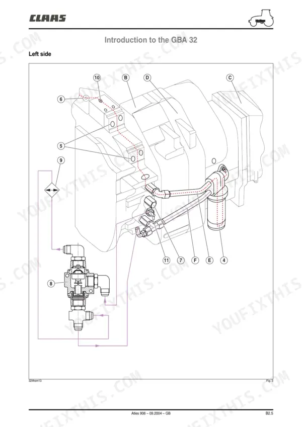
| Closed Centre Hydraulics | 290-355 | Distribution Valve, Spool Valve Block, Linkage Spool Valve, Booster Pump, Pressure Control Valve, Safety Valve |
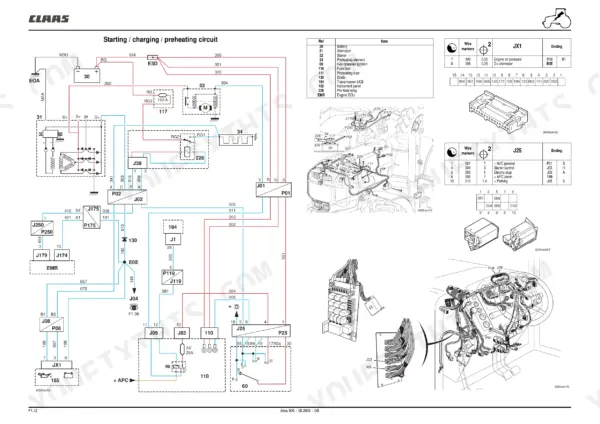
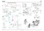
| Electrical Services | 356-474 | Fuse Box, Relay Box, Wiring Harness, Connector Grid, Harness Path |
| Instrument Panel | 475-496 | Indicator Lights, Rev Counter, Hour Counter, Fuel Gauge, Temperature Sensor, Warning Lights |
| Tce 25 Electronic Linkage | 497-506 | Position Sensor, Load Sensors, Lift Spool Valve, Solenoid Valves, Calibration Switch |
| Transmission Axle Control | 507-526 | Full Powershift, Shuttle Reverser Lever, Clutch Pedal Switches, Solenoid Valves, Speed Sensors |
| Engine Management | 527-536 | Accelerator Pedal Angle Detector, Turbocharger Pressure Sensor, Oil Pressure Sensor, Coolant Temperature Sensor, Engine Speed Sensor, Actuator |
| InfoTrac and Iso Socket | 537-550 | On-Board Computer, Iso Socket, Radar, Speed Sensor, Event Counter |
| Electropilot | 551-564 | Joystick, Spool Valve, Solenoid Valve, Control Handle, Safety Solenoid Valve |
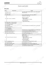
| Win Metadiag Manual | 565-611 | Engine Application, Transmission Application, Rear Lift Application, Dashboard Application, Electropilot Application, Fault History |
| Cab Lift | 612-627 | Safety Measure, Sling Specifications, Lifting Bar, Cab Removal, Cab Refitting |
| Heating Air Conditioning | 628-645 | Heating Circuit, Cooling Circuit, Compressor, Condenser, Drier, Pressure Switch, Expansion Valve, Evaporator |
| Bonding the Windows | 646-659 | Protective Equipment, Special Equipment, Consumables, Windscreen Removal, Windscreen Bonding, Ploughing Window Replacement |
| Lift and Front Power Take-Off | 660-675 | Front Linkage, Lifting Capacity, Cylinder Pressure, Front Power Take-Off Assembly, Clutch, Idler Pinion, Lower Shaft |
| Pneumatic Braking | 676-731 | Compressor, Pressure Regulator, Tank, Trailer Control Valve, Solenoid Valve, Principal Control Valve |
Quick Reference Specifications
| Specification | Value | Page |
|---|---|---|
| Space between end of rod (11) and body of switch (19) | 0,2 - 1,4 mm | p. 234 |
| Upper shaft shims play | 0.20 to 0.50 mm | p. 671 |
| Clutch feed pressure | 17 bar | p. 670 |
| Engine Cubic Capacity | 7 151 cm3 | p. 3 |
| New injector opening pressure | 250 ± 12 bar | p. 3 |
| Idle speed | 850 rpm | p. 3 |
| Rated speed | 2 200 rpm | p. 3 |
| Intake valve clearance | 0,3 mm | p. 16 |
| Exhaust valve clearance | 0,5 mm | p. 16 |
| Clutch pressure control valve | 17,2 – 19 bar | p. 79 |
| Lubricating pressure control valve | 6,2 – 9,3 bar | p. 79 |
| Gerotor pump flow rate | 110 ± 5 l/min | p. 79 |
Claas 926-936 Common Problems This Manual Covers
Claas Atles 936 rear differential lock won't engage, multidisc unit slips under load in the field
Check feed pressure to the locking device; the unit needs 17 bar to compress the discs and backplates. If pressure is low, trace the circuit for leaking seals and hoses before pulling the axle. With correct pressure and continued slip, strip the unit per the front axle procedures on page 240 and replace worn discs and backplates.
Manual Section: Front Axle p. 240Park Lock ratchet binds and won't release, tractor stuck in park with lever moving free
Remove the Park Lock cover and inspect the ratchet and toothed sleeve for burrs or broken teeth, covered on page 226. Check the control rod adjustment: the gap between the rod end and the safety switch body must measure 0,2 to 1,4 mm, per page 234. Test the solenoid valve and piston for sticking before replacing the ratchet.
Manual Section: Park Lock p. 226Powershift shifts harsh or slips between ranges once transmission oil gets hot
Test clutch pressure at the take-up points on the gearbox, procedures on page 62. The pressure control valve should hold 17,2 to 19 bar, and lubrication pressure runs 6,2 to 9,3 bar. Verify the gerotor pump delivers 110 l/min before condemning clutches; low flow points to the pump or a plugged filter, not the clutch packs.
Manual Section: Full Powershift Gearbox p. 62Whining from the hydraulic pump drive area, pump driving gear bearing worn or seized
Drain the housing and extract the pump driving gear assembly with the correct puller; forcing it damages the bearing bore. Inspect the bearing for spalling and replace the assembly if it turns rough. On reassembly, shim the upper shaft to 0.20 to 0.50 mm play, spec on page 671, and recheck end float after torquing.
Manual Section: Lift and Front Power Take-Off p. 671Hard starting and rough uneven idle, white smoke until the engine warms up
Check idle speed first; it should hold 850 rpm. Pull the injectors and pop-test them: opening pressure for new injectors is 250 bar, plus or minus 12, spec listed on page 3. Clean or replace any injector that dribbles or sprays off-pattern, then bleed the fuel system and recheck injection timing per the procedures on page 10.
Manual Section: Injection Feed p. 2Frequently Asked Questions
What are the torque specifications for the CLAAS Atles 926 drive pinion nut?
To tighten the drive pinion nut (11), use socket n 60 05 006 311 and turn the drive pinion anticlockwise to a torque of 23 ± 2 daN.m. p. 151
What is the procedure for bleeding the brake circuit on the CLAAS Atles 906?
To bleed the brake circuit manually, connect 3 flexible transparent hoses (ID 6 mm) to the bleed screws (D), (G), and (I) and immerse them in a 1-litre receptacle containing 0,5 litres of fluid (LHM). Pump the pedals about 10 times to fill the circuit, then bleed each side and the braking valve until no more air bubbles escape. p. 216
What is the correct valve clearance for the intake and exhaust valves on the Atles 926/936 engine?
The intake valve clearance is 0,3 mm and the exhaust valve clearance is 0,5 mm. These clearances must always be adjusted when the engine is cold. p. 22
What is the oil capacity for the transmission system GTA 3230?
The oil capacity for the transmission system GTA 3230 is 150 or 158 litres. p. 79
What is the tightening torque for the cylinder head screws on the Atles 906 engine?
The cylinder head screws require a pretightening value of 5 daN.m, a second phase of 13 daN.m, and a final tightening of 90 degrees. p. 35
Is this Claas Atles 926 Repair Manual a digital download?
A 731-page Repair Manual in searchable PDF format, available the moment you complete checkout. View on computer, tablet, or phone, with no shipping wait.
Can I print specific sections of this Claas Atles 926 Repair Manual?
Yes. Print the pages or sections you need for your own shop use. Any standard printer works.
Reviews
There are no reviews yet.