
All 739 pages of this Cummins QSB5.9 repair manual PDF cover the ISB and QSB5.9 engine family from cylinder block to turbocharger. Inside: a massive troubleshooting section walking you through every fault symptom, plus exploded views, rebuild sequences, and clearance tables for the cylinder head, rocker levers, fuel injection pump, lubricating oil system, cooling system, and air intake. A full specifications chapter backs every procedure with torque values across all major assemblies. Check turbocharger axial clearance between 0.038 and 0.093 mm, then torque the main bearing cap capscrews to 50 N•m [37 ft-lb] on the first pass; both figures come directly from Cummins factory spec tables. Your engine is apart on the stand. Get the right number on the first look. Jump to any section by bookmark or search any spec by keyword on laptop, tablet, or phone.
What's Inside This Cummins ISB, QSB5.9, ISB Engines, QSB5.9 Engines Repair Manual
| System | Pages | Key Topics |
|---|---|---|
| Introduction | 7-16 | Acronyms and Abbreviations (Glass or Plastic Bead Cleaning, Solvent and Acid Cleaning, Steam Cleaning, Important Safety Notice), How to Use the Manual, Illustrations, Symbols |
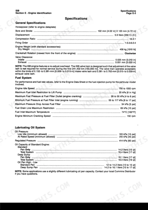
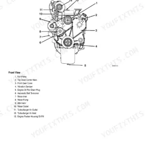
| Engine Identification | 17-28 | Engine Diagrams |
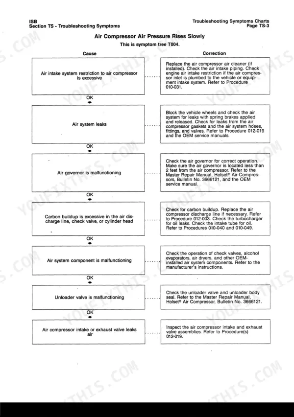
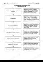
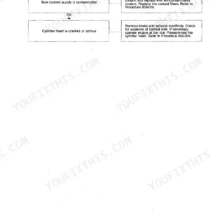
| Troubleshooting Symptoms | 29-156 | Troubleshooting Procedures and Techniques, Communication Error - Electronic Service Tool or Control Device, Coolant Temperature Above Normal - Gradual Overheat |
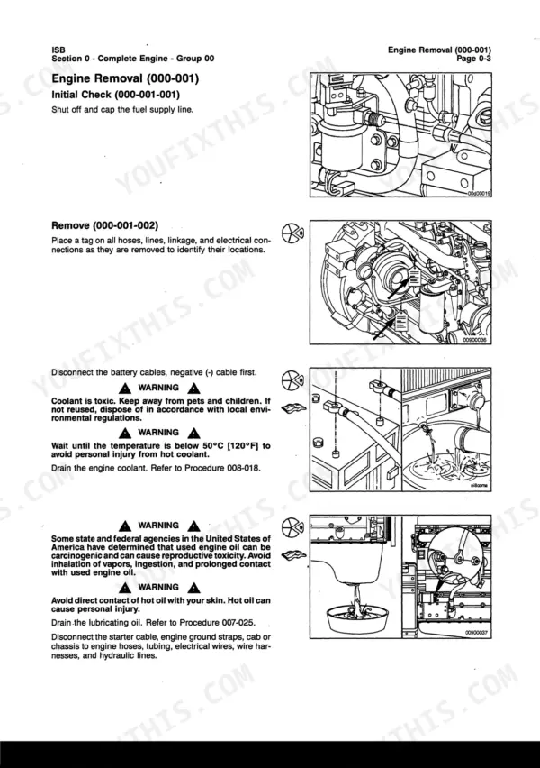
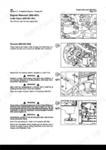
| Complete Engine | 157-170 | Engine Removal, Engine Installation |
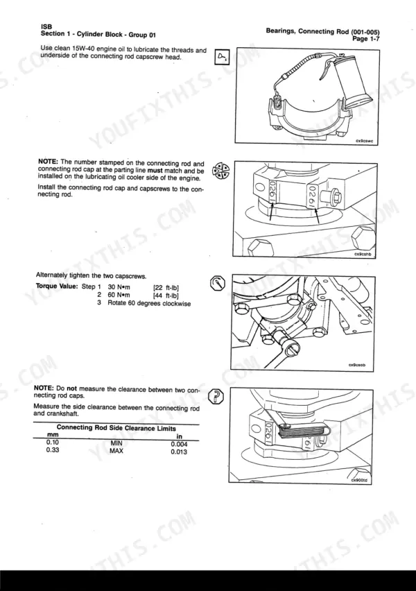
| Cylinder Block | 171-266 | Service Tools, Bearings, Connecting Rod, Main, Camshaft, Piston and Connecting Rod Assembly, Crankshaft Wear Sleeve |
| Cylinder Head | 267-300 | Service Tools, Valve |
| Rocker Levers | 301-314 | Overhead Set, Rocker Lever, Rocker Lever Cover, Crankcase Breather Tube |
| Cam Followers/Tappets | 315-326 | Service Tools, Push Rods or Tubes, Tappet |
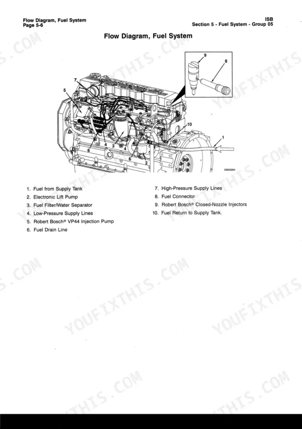
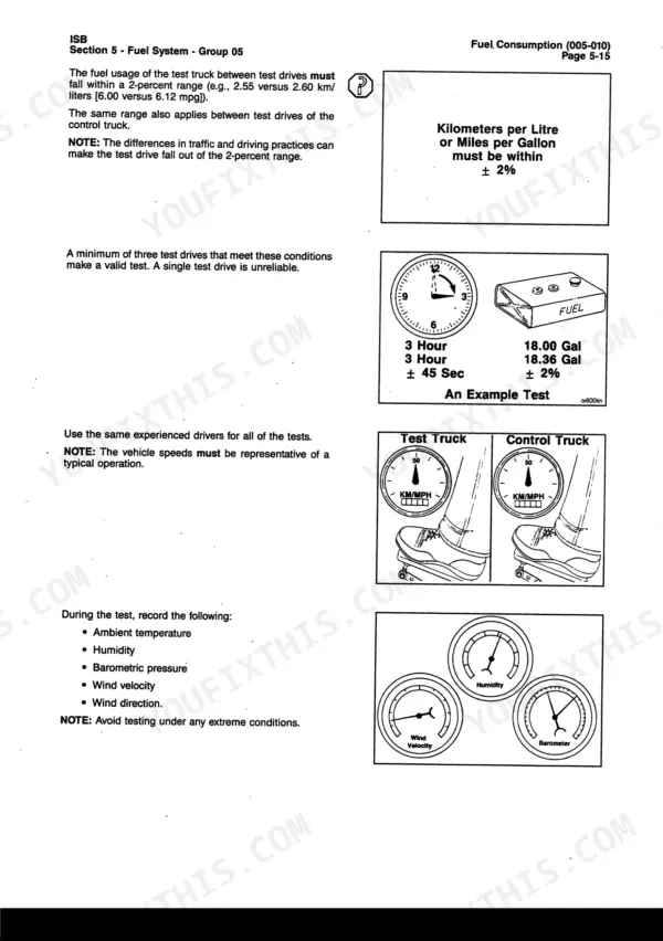
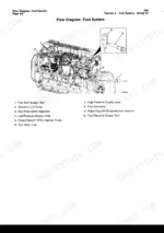
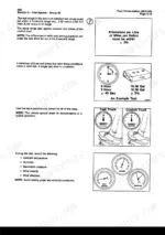
| Fuel System | 327-364 | General Information, Service Tools, Fuel Consumption, Fuel Injection Pump, Rotary, Fuel Lift Pump, Stall Speed Test, Stall Speed Checklist |
| Injectors and Fuel Lines | 365-390 | General Information, Service Tools, Fuel Drain Lines, Injector, Injector Supply Lines (High Pressure) |
| Lubricating Oil System | 391-432 | General Information, Flow Diagram, Lubricating Oil Cooler, Lubricating Oil Pump, Lubricating Oil Suction Tube (Block-Mounted) |
| Cooling System | 433-472 | Flow Diagram, Coolant Thermostat, Cooling System Diagnostics, Fan Spacer and Pulley, Fan, Cooling, Water Pump |
| Drive Units | 473-478 | Hydraulic Pump Drive, Hydraulic Pump Drive Gear and Shaft |
| Air Intake System | 479-528 | General Information, Service Tools, Air Leaks, Air Intake and Exhaust Systems, Charge Air Cooler (Cac), Turbocharger, Turbocharger Wastegate Actuator |
| Exhaust System | 529-538 | Exhaust Manifold, Dry |
| Compressed Air System | 539-576 | General Information, Service Tools, A/C Cylinder Head (Oe Models) |
| Electrical Equipment | 577-593 | Starter Switch, Starter Solenoid, Charging System Indicator |
| Engine Testing | 594-627 | General Information, Service Tools, Engine Run-In (Chassis Dynamometer), Automated Cylinder Performance Test |
| Mounting Adaptations | 628-653 | Service Tools, Flywheel, Flywheel Housing, Flywheel Ring Gear |
| Miscellaneous | 654-661 | Service Tools, Cup Plug, Pipe Plug, Straight Thread Plug |
| Vehicle Braking | 662-665 | General Information |
| Service Literature | 666-669 | Additional Service Literature, Service Literature Ordering Location |
| Component Manufacturers | 670-675 | Component Manufacturers' Addresses |
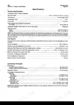
| Specifications | 676-720 | Cylinder Block - Specifications, Cylinder Block - Torque Values, Cylinder Head - Specifications, Cylinder Head - Torque Values, Rocker Levers - Specifications |
Quick Reference Specifications
| Specification | Value | Page |
|---|---|---|
| Main bearing cap capscrews torque (Step 1) | 50 N•m [37 ft-lb] | p. 185 |
| Turbocharger axial clearance (Min) | 0.038 mm [0.0015 in] | p. 510 |
| Turbocharger axial clearance (Max) | 0.093 mm [0.0037 in] | p. 510 |
| Valve stem diameter (Min) | 6.96 mm [0.2740 in] | p. 292 |
| Valve spring free length (P/N 3942095) | 43.9 mm [1.73 in] | p. 293 |
| Starter motor mounting capscrews torque | 43 N•m [32 ft-lb] | p. 589 |
| Alternator mounting capscrews torque | 24 N•m [18 ft-lb] | p. 580 |
| Turbocharger radial bearing clearance (Min) | 0.326 mm [0.0128 in] | p. 514 |
| Turbocharger radial bearing clearance (Max) | 0.496 mm [0.0195 in] | p. 514 |
| Turbocharger pre-lubrication during installation | Pour 0.25 to 0.38 cup [2 to 3 oz] of clean 15W-40 engine oil in the turbocharger oil supply line fitting | p. 509 |
| Connecting Rod Capscrew Torque (Step 1) | 30 N•m [22 ft-lb] | p. 685 |
| Cylinder Head Capscrews (Step 1) | 80 N•m [59 ft-lb] | p. 689 |
Cummins ISB, QSB5.9, ISB Engines, QSB5.9 Engines Common Problems This Manual Covers
Rough idle, power loss, and unusual valve noise after extended hours between overhead adjustments
Rotate the crankshaft to position each cylinder at TDC on the compression stroke; follow the Overhead Set sequence at page 301. Inspect valve stems: minimum diameter is 6.96 mm [0.2740 in]. Check valve spring free length on page 293. Torque head capscrews to 80 N•m [59 ft-lb], then 105 N•m [77 ft-lb], then rotate 90 degrees clockwise.
Manual Section: Rocker Levers p. 301No oil pressure at turbocharger after reinstallation, shaft seizes on first engine start
Before connecting the oil supply line, pour 0.25 to 0.38 cup [2 to 3 oz] of clean 15W-40 engine oil into the turbocharger oil supply line fitting per page 509. Rotate the shaft by hand to distribute oil through the bearings. Connect the oil line, crank the engine without starting for 30 seconds, then verify oil pressure before firing.
Manual Section: Air Intake System p. 509Starter motor does not spin or turns over slowly, battery drains with engine off
Check battery voltage and cable connections first, then inspect the starter solenoid at page 577. If the starter is confirmed failed, replace it and torque mounting capscrews to 43 N•m [32 ft-lb]. For overnight drain with the engine off, test alternator diodes for reverse leakage. Replace the alternator if diodes fail; torque bracket capscrews to 24 N•m [18 ft-lb].
Manual Section: Electrical Equipment p. 577Engine cranks but fails to start, no fault codes stored and battery voltage confirmed good
Verify cranking fuel pressure against the diagnostic test values at page 343. Inspect the fuel filter for restriction and test fuel lift pump output. Work through the troubleshooting procedures: ECM function, fuel delivery, and injector supply in sequence. Check all fuel line connections for air ingestion at cracked fittings or loose clamps.
Manual Section: Fuel System p. 343Frequently Asked Questions
What are the torque specs for Cummins ISB main bearing bolts?
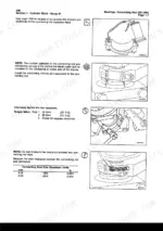
The torque specifications for the main bearing capscrews are a three-step process: first, tighten to 50 N•m [37 ft-lb]; second, tighten to 60 N•m [44 ft-lb]; and finally, turn all capscrews through 90 degrees clockwise. p. 685
What are the replacement specifications for Turbocharger (Complete assembly with bearings and seals)?
The manual provides inspection specifications for turbocharger components, such as axial clearance (MIN 0.038 mm, MAX 0.093 mm) and radial bearing clearance (MIN 0.326 mm, MAX 0.496 mm). If these clearances are not met, the turbocharger should be replaced. The installation torque for the turbocharger mounting nuts is 45 N•m [33 ft-lb]. p. 508
What are the replacement specifications for Cylinder Head (Valves, springs, and seals)?
For valve springs, the approximate free length for part number 3942095 is 43.9 mm [1.73 in] with a maximum inclination of 1.5 mm [0.059 in]. For part number 3943161, the approximate free length is 47.75 mm [1.88 in] with a maximum inclination of 1.5 mm [0.059 in]. During valve seal installation, compress springs to 24.9 mm [0.98 in]. p. 288
How do you fix cummins QSB5.9 turbocharger shaft axial play exceeds tolerance, oil residue coating compressor or turbine wheels?
Measure turbocharger axial clearance at the shaft: spec is 0.038 to 0.093 mm [0.0015 to 0.0037 in] per page 510. Check radial bearing clearance at page 514; limit is 0.326 to 0.496 mm [0.0128 to 0.0195 in]. If either reading is out of range, replace the complete turbocharger assembly and torque mounting nuts to 45 N•m [33 ft-lb]. p. 510
What format is this manual in?
Immediate download of the complete 739-page searchable Repair Manual. Access it on any device, from a laptop at your desk to a phone in the field.
Can I print this manual?
No restrictions at all. Print individual pages, full chapters, or the entire manual. The PDF is completely unlocked.


Reviews
There are no reviews yet.