
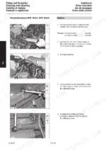
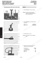
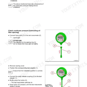
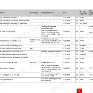
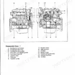
From crankcase and crankshaft through injection pump timing, cylinder head, valve gear, cooling and lubrication, this 512-page Deutz BF4M 1012 workshop manual PDF (OEM 0297 9771) walks the whole 1012 and 1013 diesel engine family, ten variants, E versions included. Repair of components fills roughly a third of the book (crankshaft, connecting rod, piston, camshaft, rocker arm bracket), and a complete disassembly and reassembly section rebuilds your engine in order, from mass balancing shafts to TDC determination and control rod travel. Up front sit the valve lash schematic, the cylinder head bolt tightening order and the Bosch pump shim tables. On a BFM 1012, bring the main bearing bolts to 30 Nm, then turn them 60° and a further 60°; lube oil cooler bolts take 20 Nm. A rebuild stalls fast over one missing shim thickness. Bookmarked, text-searchable pages put that table in front of you, so you order the correct shim the first time.
What's Inside This Deutz BFM 1012/1013 Manual
| System | Pages | Key Topics |
|---|---|---|
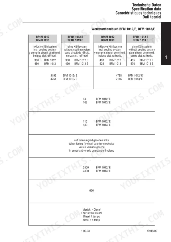
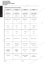
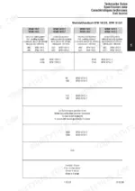
| Specification Data | 9-74 | Schematic for Valve Clearance Adjustment, Tightening Order for Cylinder Head Bolts |
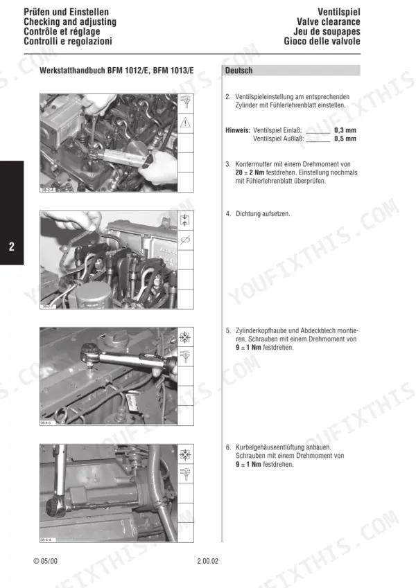
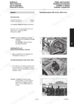
| Checking and Adjusting | 75-92 | Valve Clearance, Compression Pressure, Injector |
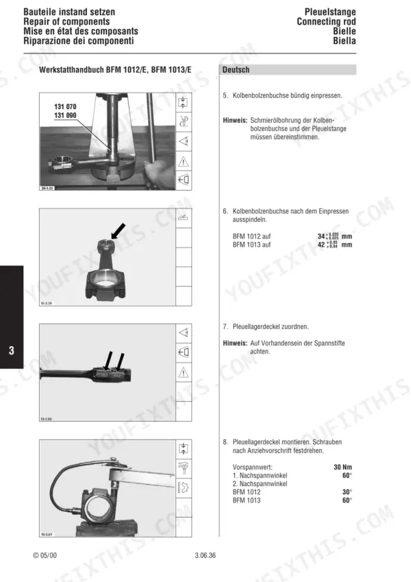
| Repair of Components | 93-264 | Crankcase, Front Cover and Lube Oil Pump, Crankshaft, Connecting Rod, Piston, Cylinder Head, Camshaft, Rocker Arm Bracket |
| Engine Disassembly | 265-303 | Oil Spray Nozzles, Tappets, Camshaft, Crankshaft Bearings |
| Engine Reassembly - Internal Components | 304-333 | Oil Spray Nozzles, Crankshaft Installation, Mass Balancing Shafts, Camshaft Installation, Piston and Connecting Rod Assembly |
| Injection Pump Installation | 334-347 | Injection Pump Timing, Control Rod Travel, TDC Determination |
| Cylinder Head and Valve Gear | 348-371 | Cylinder Head Gasket, Cylinder Head Installation, Valve Gear, Exhaust Manifold, Intake Manifold |
| Cooling and Lubrication System Components | 372-413 | Lube Oil Cooler, Coolant Pump, Oil Suction Pipe, Oil Pan, Thermostat |
| Auxiliary Equipment and Final Assembly | 414-496 | Alternator, V-Belt Tensioning, Air Compressor, Hydraulic Pump, Injection Pump Replacement |
| Tools | 497-512 | Commercial Tools, Special Tools |
Quick Reference Specifications
| Specification | Value | Page |
|---|---|---|
| BFM 1012 | ||
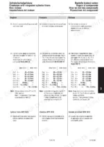
| Initial tightening torque | 30 Nm | p. 98 |
| 1st tightening angle | 60° | p. 98 |
| All Models | ||
| Lube oil cooler fastening bolts torque | 20 Nm | p. 194 |
| Collar screws initial tightening | 80 Nm | p. 200 |
| V-belt pulley bolt torque | 21 Nm | p. 232 |
| Central bolt torque for rotor and V-belt pulley | 120 Nm | p. 244 |
| Cover bolt torque | 9 Nm | p. 244 |
| Charge air pipe bolt torque | 11 ± 1 Nm | p. 371 |
| Coolant pump bolt torque | 21 ± 2 Nm | p. 373 |
| Exhaust turbocharger BFM 1012 mounting bolts torque | 21 ± 2 Nm | p. 398 |
| BFM 1013 | ||
| Cylinder head bolts (BFM 1013) | 1st stage 30 Nm, 2nd stage 80 Nm, 90° | p. 360 |
| BFM 1013/E | ||
| Cylinder head bolts (BFM 1013/E) | 1st stage 50 Nm, 2nd stage 130 Nm, 90° | p. 362 |
Deutz BFM 1012/1013 Common Problems This Manual Covers
Deutz BFM 1012 and 1013 valve clearance out of specification on inlet or exhaust valves during check
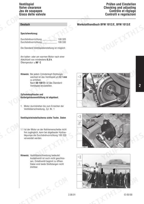
Adjust valve clearance following the procedure on page 80, working from the valve clearance adjustment schematic in Specification Data. Set inlet valves to 0.3 mm and exhaust valves to 0.5 mm; the procedure covers a cold or warm engine. Recheck every cylinder after adjusting and before final assembly.
Manual Section: Valve Clearance Adjustment p. 80Low compression pressure readings on one or more cylinders during a compression pressure test
Test compression on each cylinder following the procedure on page 84 and compare every reading against the limit values. On a BFM 1012, expect 28-33 bar. If a cylinder reads low, verify valve clearance first, then measure the cylinder bores and inspect the valve seats once the engine is apart.
Manual Section: Compression Pressure Measurement p. 84Injector fails opening pressure check, buzzing test, or shows poor spray pattern on the bench
Test each injector following page 86: check opening pressure first, then run the buzzing and spray pattern test and the tightness test. On a BFM 1012, opening pressure is 250 + 8 bar. Reject any injector that drips during the tightness test or sprays a ragged pattern, and retest after service before refitting.
Manual Section: Injector Testing p. 86Crankcase cylinder bores worn or out of limit when measured during engine teardown
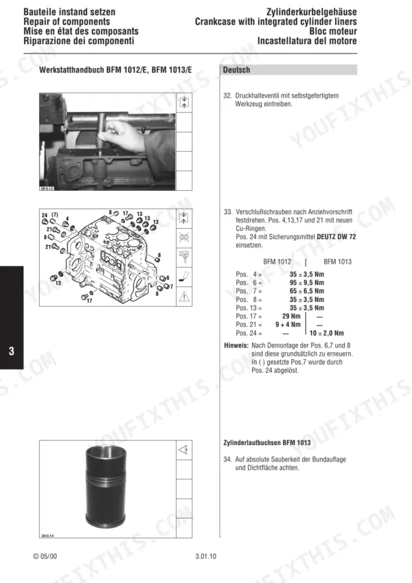
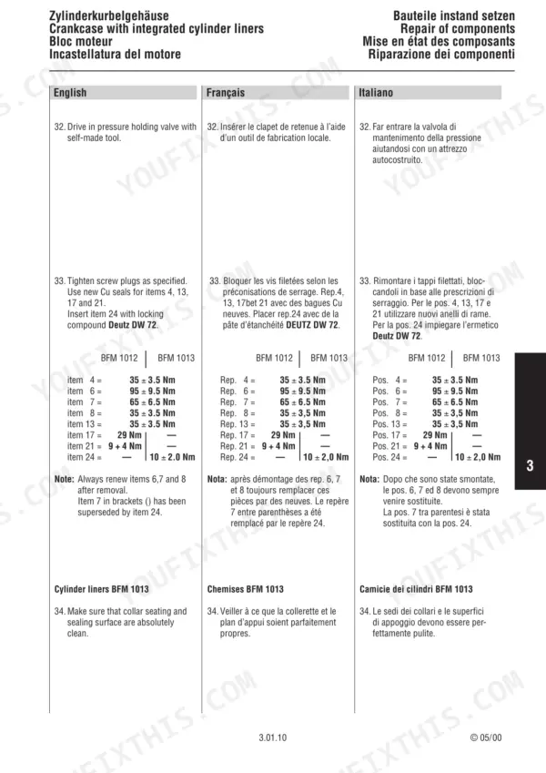
Measure every cylinder bore per the Crankcase Repair procedure, and remove liners where the bore is out of limit. Replace worn bearing bushes while the block is bare. When fitting main bearing caps on a BFM 1012, torque to 30 Nm following page 98, then turn a 60° first pass and a 60° second pass.
Manual Section: Crankcase Repair p. 98Crankshaft journals worn or runout over limit when measured on the bench
Measure each crankshaft journal and compare the readings against the undersize limits in the Crankshaft Repair section before choosing an undersize. Check runout next; on a BF4M engine the limit is 0.07 mm per page 138. Do not put a crank back in the block if it measures outside that limit.
Manual Section: Crankshaft Repair p. 138Cylinder head valve stem clearance excessive, valve seats worn, or valve springs short on inspection
Measure valve stem clearance, rework worn valve seats, and check valve spring length per the Cylinder Head Repair procedure. Fit a new cylinder head gasket and follow the head bolt tightening order in Specification Data. Verify which torque stages apply before you start: the BFM 1013 and BFM 1013 E values differ on pages 360 and 362.
Manual Section: Cylinder Head RepairFrequently Asked Questions
What are the torque specifications for the cylinder head bolts on the Deutz BFM 1012?
For the BFM 1012, the cylinder head bolts are tightened in two stages, first to 30 Nm and then to 80 Nm, followed by a final tightening angle of 90°. The tightening order is shown on page 24, and the tightening steps are on page 360. p. 360
What are the torque specifications for the main bearing bolts on the Deutz BFM 1013?
For the BFM 1013, the initial tightening torque for the main bearing bolts is 50 Nm, followed by two tightening angles of 60° each. Refer to page 99 for the specific tightening procedure. p. 99
What is the standard valve clearance for the Deutz BFM 1012/1013 engines?
The standard valve clearance for the inlet valve is 0.3 mm and for the exhaust valve is 0.5 mm. These should be adjusted with the engine cold or warm after a cooling period of at least 0.5 hours. p. 80
What is the compression pressure for the Deutz BFM 1012 and BFM 1013 engines?
The compression pressure for the BFM 1012 is 28-33 bar, and for the BFM 1013 it is 30-38 bar. Measurements should be taken as a comparison between all cylinders in one engine. p. 84
What is the opening pressure for the injectors on the Deutz BFM 1012 and BFM 1013?
The opening pressure for the BFM 1012 injector is 250 + 8 bar, and for the BFM 1013 it is 275 + 8 bar. These values are used when checking the opening pressure on a nozzle tester. p. 86
Will this Deutz BFM 1012 Workshop Manual download right away?
Instant PDF download. You get the full 512-page searchable Workshop Manual immediately after payment. Open it on your laptop, tablet, or phone right in the shop.
Is this Deutz BFM 1012 Workshop Manual printable?
Yes. Printing works from any reader and any printer, for your own shop use.


Reviews
There are no reviews yet.