
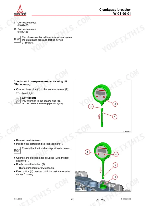
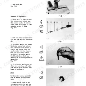
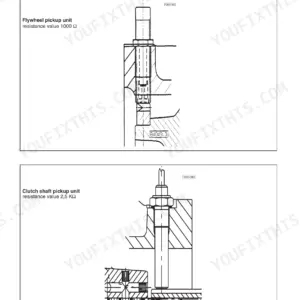
A TCD 2.9 L4 with low compression or a weeping rail fitting sits on the stand until you can put factory numbers to it, and this Deutz TCD 2.9 L4 service manual PDF, the 206-page shop manual issued under OEM ID 0312 5201 en, is where those numbers live. Job cards walk each repair from crankcase pressure testing through high-pressure pump, injector, and rail removal to the assembly order for the DOC and SCR catalysts. A special tools chapter names the compression gauge, turning gear, and locking device before you need them, so nothing waits on an improvised fixture. Torque the cylinder head cover screws to 8.5 Nm, the injector clamping claw to 30 Nm, and the exhaust gas recirculation module screws to 20 Nm. One missing figure can park an engine for a week. Pay once for this bookmarked, text-searchable PDF and it belongs to you for as long as the engine does.
What's Inside This Deutz TCD 2.9 L4 Manual
| System | Pages | Key Topics |
|---|---|---|
| Workshop Manual | 1-5 | Crankcase, Oil Pan, Crankshaft, Cylinder Head, Gear Case, Fuel Injector |
| General | 6 | Intended Use, Maintenance and Care Requirements, DEUTZ Original Parts, Warranty Conditions |
| Safety Information / User Information | 7-12 | Personnel Training, Engine Room Safety, Common Rail Systems, Exhaust After-Treatment, Electrical System, Disposal Regulations |
| Special Tools | 13-25 | Compression Gauge, Assembly Pliers, Socket Wrench Insert, Multi-Tooth Socket Wrench, Force Multiplier, Crankcase Pressure Testing Device |
| Crankcase/Front Cover | 26-37 | Check Crankcase Pressure, Removing and Installing the Control Valve, Sealing Parts (Crankcase, Oil Filler Neck), Oil Measuring Device |
| Oil Pan | 38-43 | Removing and Installing the Lubricating Oil Pan |
| Crankshaft/Torsional Vibration Damper/ | 44-53 | Removing and Installing the Drive Flange, Removing and Installing the Flywheel (Fastening Parts), Fastening Parts (Pulley - Drive Flange) |
| Cylinder Head | 54-61 | Checking the Compression Pressure (When Injectors Are Removed), Removing and Installing the Cylinder Head Cover |
| Gear Case/Gear Drive | 62-74 | Replacing the Crankshaft Sealing Ring (Flywheel Side), Removing and Installing the Sealing Cover, Removing and Fitting the Front Cover (Fastening Parts) |
| Lubricating Oil Cooler/Lubricating Oil Filter | 75-77 | Removing and Installing the Lubricating Oil Cooler, Lubricating Oil Filter Installation |
| Lubricating Oil Pipe | 78-79 | Removing and Installing the Oil Suction Pipe |
| Injection Pump/High Pressure Pump | 80-87 | Removing and Installing the High-Pressure Pump |
| Fuel Injector/Injector | 88-94 | Removing and Installing the Injector |
| Fuel Filter/Fuel Pump | 95-103 | Fuel Pre-Filter, Fuel Filter, Pressure Sensor Installation (Fuel Pressure), Level Sensor (Fuel Pre-Filter) |
| Fuel Pipes | 104-121 | Removing and Installing the Rail, Removing and Installing the Pressure Relief Valve (Rail), Removing and Installing the Rail Pressure Sensor |
| Air Filter/Suction Pipe/Charge Air Line | 122-127 | Removing and Installing the Charge Air Line, Intake Nozzle (Exhaust Turbocharger), Charge Air Manifold |
| Coolant Pump | 128-132 | Removing and Installing the Coolant Pump, V-Belt Pulley (Fastening Parts, Coolant Pump) |
| Coolant Pipes/Thermostat Housing | 133-137 | Removing and Installing the Thermostat, Checking the Thermostat (When Removed) |
| Exhaust Pipe/Exhaust Gas Recirculation | 138-152 | Removing and Installing the Exhaust Pipe, Removing and Installing the Flutter Valve, Removing and Installing the Exhaust Gas Recirculation Module |
| Exhaust Gas Turbocharger | 153-165 | Removing and Installing the Exhaust Gas Turbocharger, Removing and Installing the Lubricating Oil Line (Exhaust Turbocharger) |
| Generator/Starter | 166-170 | Removing and Installing the Generator, Generator, Starter |
| Electric | 171-174 | Fastening Parts (Cable Harness, Transfer Connector, Crankcase), Pressure Sensor Installation (Fuel Pressure / Lubricating Oil Pressure), Cable Harness |
| Tools/Special Tools | 175-179 | Check Cooling System for Leaks, Removing and Installing Turning Gear/Locking Device |
| Measuring Instruments | 180-194 | Removing and Installing the Speed Sensor (Crankshaft), Removing and Installing the Speed Sensor (Camshaft), Removing and Installing Pressure/Temperature Sensor (Charge Air) |
| Connection Housing | 195-196 | Installing and Removing the Connection Housing |
| Exhaust Gas Treatment | 197-206 | Order of Assembly (Installing Catalyst) DOC (Diesel Oxidation Catalyst), SCR (Selective Catalytic Reduction), Holder (Module Size 13"), Holder (Module Size 5.66") |
Quick Reference Specifications
| Specification | Value | Page |
|---|---|---|
| clamping claw screw | 30 Nm | p. 56 |
| tightening torque for cylinder head cover screws | 8.5 Nm | p. 61 |
| Tighten screw (2) | 30 Nm | p. 93 |
| Tightening torque for exhaust gas recirculation module screws | 20 Nm | p. 146 |
| Tightening torque for exhaust gas recirculation valve screws | 8 Nm | p. 151 |
| Pressure sensor | 25 Nm | p. 173 |
| Pressure sensor tightening torque | 25 Nm | p. 193 |
| Compression gauge measuring range | 10-40 bar | p. 13 |
| Control valve locking screw torque | 65 Nm | p. 33 |
| Crankcase sealing parts locking screw torque | 60 Nm | p. 34 |
| Lubricating oil pan locking screw torque | 55 Nm | p. 43 |
| Drive flange central screw stage 1 torque | 130 Nm | p. 48 |
Deutz TCD 2.9 L4 Common Problems This Manual Covers
Deutz TCD 2.9 L4 starts then shuts down after a few minutes, rail pressure fault active
Check the fuel pre-filter and main filter for restriction, procedures start on page 95. Bleed air from the supply side and watch rail pressure while cranking. If the rail pressure sensor reads suspect, replace it per page 114 and torque it to 70 Nm. Inspect injector return lines for excess flow before condemning the high-pressure pump.
Manual Section: Fuel Filter/Fuel Pump p. 95Hard starting or no start when cold, cranks normally with weak or no smoke
Test compression with the injectors removed, procedure on page 54. Use the compression gauge from the special tools list on page 13; its measuring range is 10 to 40 bar. Compare cylinders against each other and pull the cylinder head cover to check valve lash if readings run low. Torque the cover screws to 8.5 Nm on reassembly.
Manual Section: Cylinder Head p. 54Fault code 1026 with a low oil pressure warning at idle, engine shuts itself down
Verify oil level and grade first. Test the oil pressure sensor before tearing anything down; sensor removal is under measuring instruments starting on page 180, and the new sensor torques to 25 Nm. If pressure truly reads low, inspect the oil suction pipe per page 78, then remove the oil pressure control valve and reinstall it at 60 Nm.
Manual Section: Measuring Instruments p. 193EGR valve fault codes 1019 through 1025, derate with rough running at low load
Check the EGR valve harness and connector for chafed wiring before replacing parts; codes 1019 and 1020 flag shorts, not always a dead valve. Remove the valve per the procedure starting on page 138 and inspect for soot binding the actuator. Torque valve screws to 8 Nm and module screws to 20 Nm on reinstall.
Manual Section: Exhaust Pipe/Exhaust Gas Recirculation p. 138Exhaust temperature codes 1302 or 1617 downstream of DOC, repeated derate during regeneration
Test both temperature sensors at the DOC; code 1617 flags both reading defective, and two sensors rarely die together, so check the harness first. Find sensor removal steps under measuring instruments starting on page 180. Inspect the exhaust pipe for leaks upstream of the DOC and retorque pipe screws to 55 Nm per page 139.
Manual Section: Measuring Instruments p. 180Frequently Asked Questions
How do I read error codes on the Deutz TCD 2.9 engine?
To read error codes, you must use the diagnostic tool SerDia 2010. The manual specifies that you should read out the error log on the engine control unit using this tool. p. 54
What are the replacement specifications for the exhaust gas recirculation valve on the Deutz TCD 2.9 L4 engine?
The exhaust gas recirculation valve must be replaced if it is leaking. When installing, the screws must be tightened to 8 Nm, and you must use new O-rings (1) and (2) coated with mounting compound. p. 151
What is the tightening torque for the oil pan screws on a Deutz TCD 2.9 L4 engine?
The lubricating oil pan screws must be tightened to 21 Nm following the specified tightening sequence. Additionally, the locking screw for the oil pan must be tightened to 55 Nm. p. 43
What is the procedure for checking compression pressure on a Deutz TCD 2.9 L4 engine?
Compression pressure is checked using a compression gauge (01899034) with a measuring range of 10-40 bar. The check must be performed on all cylinders consecutively, and if a deviation of more than 15% is found, the cylinder unit must be disassembled. p. 57
What is the tightening torque for the high-pressure pump gear wheel nut on a Deutz TCD 2.9 L4 engine?
The nut for the high-pressure pump gear wheel must be tightened to 80 Nm while holding the gear wheel in a vice using aluminium protective jaws. p. 84
What do I get after purchasing this Deutz TCD 2.9 L4 manual?
This is a 206-page searchable PDF ready for immediate download. Works on any device, so pull it up on your phone while you're under the hood. No shipping, no waiting.
Is printing allowed for this Deutz TCD 2.9 L4 Service Manual?
Yes. No DRM, nothing blocks printing, so run off the pages you need on whatever printer you have.

Reviews
There are no reviews yet.