

Part of the Doosan Repair Manuals.
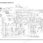
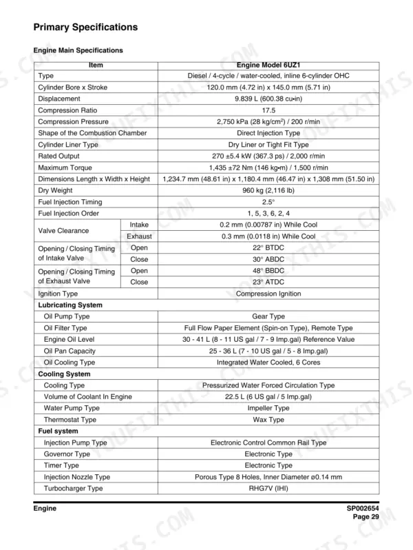
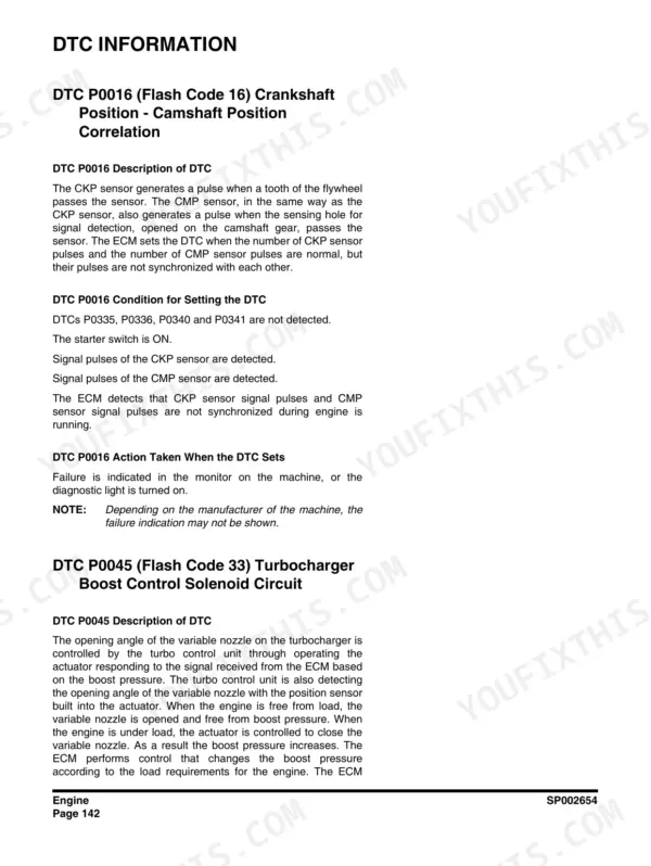
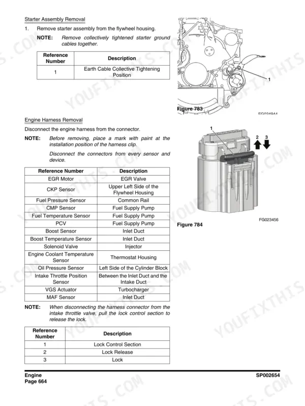
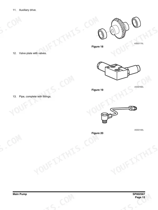
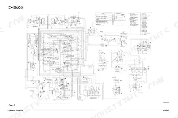
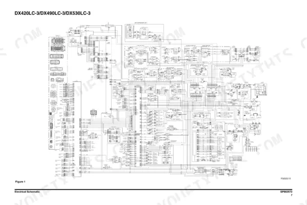
This is the factory shop manual for the Doosan DX420LC-3 crawler excavator, publication 950106-00398E, July 2012 edition. It covers the whole 41,350 kg machine: the Isuzu 6UZ1 inline six rated 270 kW (367 hp), the A8VO200 main pump, main control valve, swing and travel devices, cylinders, the full electrical system, and boom/arm removal. The engine section alone runs from basic specs through compression testing, fuel system checks, DPD control, and a dedicated DTC Information sub-chapter spanning pages 378 to 455. You also get a complete hydraulic schematic (page 1705) and electrical schematic (page 1869). If you are rebuilding a pump, chasing a fault code, or pulling the counterweight, this is the book Doosan techs used.
What's Inside This Manual
| System | Pages | Key Topics |
|---|---|---|
| Safety | 5-72 | Track Excavator Maintenance Safety, Safety Messages, Signal Words, Other Signal Words, Safety Decals, Safe Operation Is Operator's Responsibility |
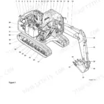
| Specifications and General Maintenance | 73-138 | Specification for DX420LC-3, General Description, Component Locations, Overall Dimensions, Working Range, General Specifications |
| Upper Structure and Lower Structure and Chassis | 139-234 | Cabin, Cabin Identification, Rollover Protective Structure (ROPS), Removal, Installation, Counterweight |
| Engine and Drivetrain - Service Information Guide | 235-259 | Engine, Safety Information, Service Information Guide, Contents Included in Service Information, Plastic Gauge, Recommended Liquid Gasket |
| Engine and Drivetrain - Maintenance Information | 260-338 | Maintenance Information, Maintenance Precautions, Primary Specifications, Function, Structure, Operation, Introduction to the Trouble Diagnosis |
| Engine and Drivetrain - Functional Inspection and Symptom | 339-377 | Functional Inspection, Engine Compression Pressure Inspection, Fuel System Check, Air Intake System Check, Exhaust System Check, DPD Control System Check |
| Engine and Drivetrain - DTC Information | 378-455 | DTC Information, DTC P0016 (Flash Code 16) Crankshaft Position - Camshaft Position Correlation, DTC P0045 (Flash Code 33) Turbocharger Boost Control Solenoid Circuit, DTC P0087 (Flash Code 225) Fuel Rail/ System Pressure - Too Low, DTC P0088 (Flash Code 118) Fuel Rail/ System Pressure - Too High, DTC P0089 (Flash Code 151) Fuel Pressure Regulator Performance |
| Engine and Drivetrain - Engine Control | 456-601 | Engine Control, DTC P0016 (Flash Code 16) Crankshaft Position - Camshaft Position Correlation, DTC P0045 (Flash Code 33) Turbocharger Boost Control Solenoid Circuit, DTC P0087 (Flash Code 225) Fuel Rail/ System Pressure - Too Low, DTC P0088 (Flash Code 118) Fuel Rail/ System Pressure - Too High, DTC P0089 (Flash Code 151) Fuel Pressure Regulator Performance |
| Engine and Drivetrain - Mechanical | 602-962 | Mechanical, Cylinder Head Cover, Cylinder Head Assembly, Idle Gear, Cylinder Block, Crankshaft |
| Engine and Drivetrain - Fuel System | 963-1023 | Fuel System, Fuel Supply Pump, Injector, Common Rail Assembly, Fuel Filter, Pressure Limiter |
| Engine and Drivetrain - Cooling and Lubrication | 1024-1090 | Cooling, Water Pump Assembly, Thermostat, Radiator, Overheat Switch, Engine Coolant Temperature Sensor |
| Engine and Drivetrain - Induction to Electrical | 1091-1164 | Induction, Boost Temperature Sensor, Turbocharger Assembly, Intercooler, Air Cleaner Filter, IMT Sensor |
| Engine and Drivetrain - Wiring Diagram to Drive Coupling (Main Pump) | 1165-1218 | Wiring Diagram, Using the Wiring Diagram, Location Diagram, Engine, Connector List, Engine Coolant Heater (Option) |
| Hydraulics - Hydraulic System Troubleshooting, Testing and Adjustment to Center Joint (Swivel) | 1219-1276 | Hydraulic System Troubleshooting, Testing and Adjustment, Hydraulic System - General Notes, Hydraulic Schematic, General Notes, Operation of Working Components, Boom Operating Circuit |
| Hydraulics - Cylinders and Swing Device | 1277-1370 | Cylinders, General Description, Theory of Operation, Parts List, Special Tools and Materials, Piston Nut |
| Hydraulics - Travel Device | 1371-1430 | Travel Device, Basic Structure and Drawings, Operation Principle, Operation Instructions, Troubleshooting, Maintenance Instructions |
| Hydraulics - Main Pump | 1431-1486 | Main Pump, Sectional View, A8VO200LA1KH1/63, General Repair Guidelines, Seal Kits and Subassemblies, Sealing the Driveshaft |
| Hydraulics - Gear Pump to Fan Pump | 1487-1566 | Gear Pump, Disassembling Single Gear Pump (Opt), Reassembling Single Gear Pump (Opt), Fan Motor for Oil Cooler, Disassembly, Assembly |
| Hydraulics - Main Control Valve | 1567-1624 | Main Control Valve, General Description, When All Spools Are in Neutral, Single Operation, Combined Operation, Antidrift Valve |
| Hydraulics - Remote Control Valve (Work Lever / Joystick) to Hydraulic Schematic | 1625-1706 | Remote Control Valve (Work Lever / Joystick), General Description, Theory of Operation, Parts List, Specifications, Torques |
| Electrical System | 1707-1870 | Electrical Supply System, Engine Starting Circuit, Start Operation, After Start, Engine Preheating System |
| Attachments | 1871-1902 | Boom and Arm, Front Attachment Pin Specifications, DX420LC-3, Front Attachment - Removal and Installation, Arm Removal Procedure, Boom Removal Procedure |
Quick Reference Specifications
| Specification | Value | Page |
|---|---|---|
| Engine model | Isuzu 6UZ1, inline 6-cylinder | p. 265 |
| Rated power | 270 kW (367 hp) | p. 265 |
| Shipping weight, standard track | 41,350 kg (91,161 lb) | p. 88 |
| Counterweight | 8,200 kg (18,078 lb) | p. 88 |
| Standard boom weight | 3,098 kg (6,829 lb) | p. 88 |
| Fuel tank capacity | 640 liters (169 U.S. gal) | p. 88 |
| Optional shoe weight penalty | add 720 kg (1,590 lb) for 750 mm (30") shoes | p. 88 |