
Part of the Doosan Repair Manuals.
The Doosan factory shop manual for the DX225LC-5 crawler excavator, publication 950106-01107E, serial number 1001 and up, 1,356 pages.
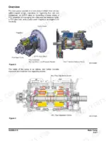
It runs the machine end to end - safety and general maintenance, specifications, the Doosan DL06 diesel, then an unusually deep Upper Structure section: cabin and ROPS, counterweight, hydraulic oil and fuel tanks, the axial piston main pump with its theory of operation, the drive coupling, the main control valve, the swing device, joystick and travel control valves, solenoid and EPPR valves and the accumulator. Lower structure and chassis cover the swing bearing, centre joint and track gear; Front covers boom, arm and bucket removal and installation; then the hydraulic system with its component and oil-flow charts, the electrical system from supply through engine start, and an Options section.
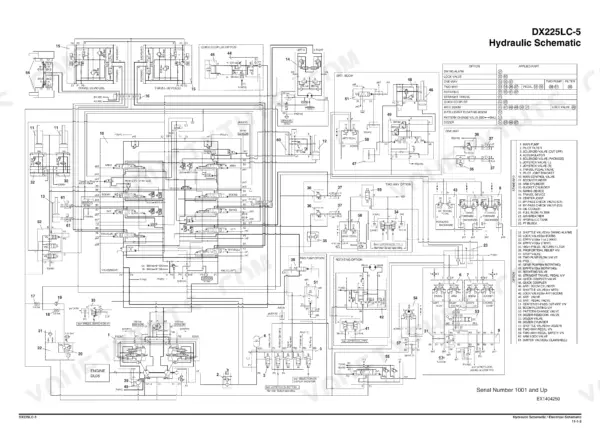
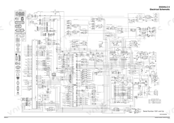
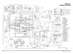
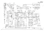
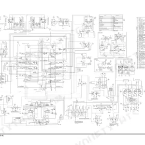
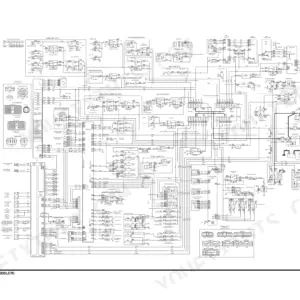
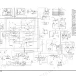
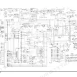
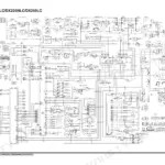
The book closes with two full fold-out sheets: the DX225LC-5 hydraulic schematic on page 1355 (drawing EX1404250, 61-item component legend and an option matrix) and the electrical schematic on page 1356 (drawing EX1404254, with the connector and terminal legend).
What's Inside This Doosan DX225LC-5 Manual
| System | Pages | Key Topics |
|---|---|---|
| Safety | 1-74 | Track Excavator Maintenance Safety, Safety Instructions, Safety Messages, General, Safe Operation Is Operator's Responsibility, Know Your Machine |
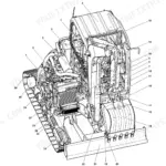
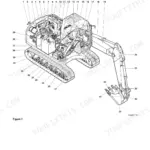
| Specifications | 75-108 | General Description, Component Locations, Overall Dimensions, One - Piece Boom, Two - Piece Boom, Working Range |
| General Maintenance | 109-146 | General Maintenance Instructions, Welding Precautions and Instructions, Hydraulic System - General Precautions, Maintenance Service and Repair Procedure, General Precautions, Hydraulic System Cleanliness and Oil Leaks |
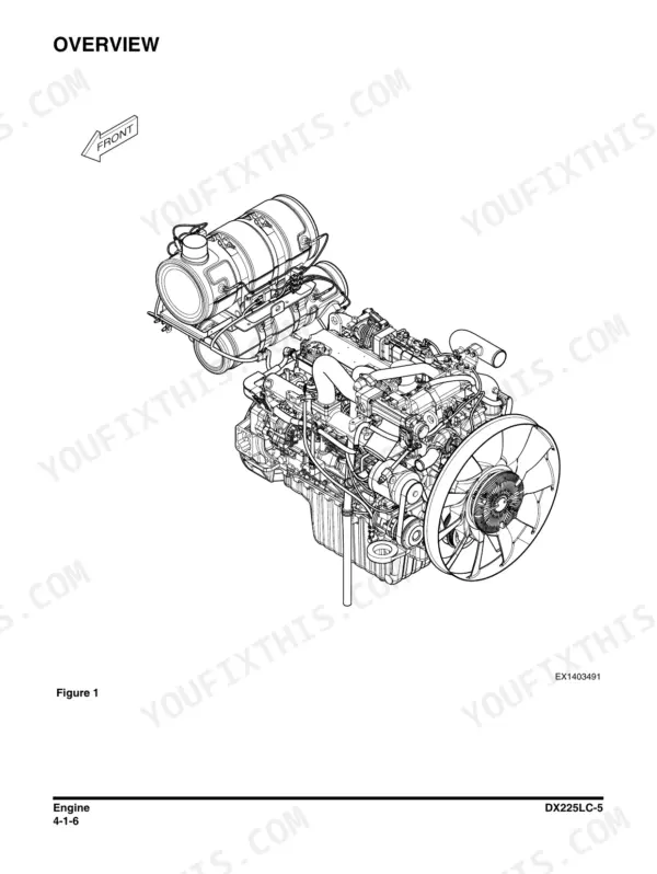
| Engine | 147-344 | Overview, General Information, Engine Maintenance, Inspection and Repair of the Engine, Engine Identification, Engine Data Plate |
| Upper Structure - Cabin | 345-370 | Cabin Identification, Roll-Over Protective Structure (ROPS), Removal, Installation, Completing Work, Dimensions of Cabin Glass |
| Upper Structure - Counterweight | 371-380 | Counterweight Removal Warning, Safety Instructions, Removal Procedure, Installation Procedure |
| Upper Structure - Hydraulic Oil Tank | 381-398 | Specification, Parts List, Air Breather |
| Upper Structure - Fuel Tank | 399-414 | Fuel Tank Specification, Parts List, Removal, Installation, Safety Instructions |
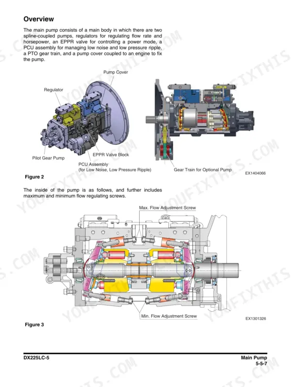
| Upper Structure - Main Pump | 415-482 | Axial Piston Pump, Specifications, Theory of Operation, Cautions for Operation, Tools, Tightening Torque |
| Upper Structure - Drive Coupling (Main Pump) | 483-494 | Coupling Specification, Parts List, Section View, Tools, Disassembly, Reassembly |
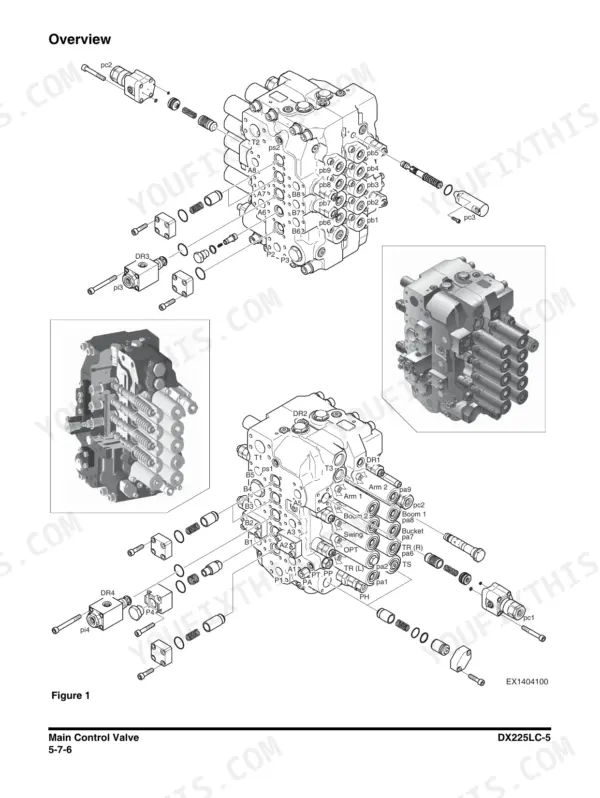
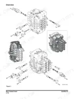
| Upper Structure - Main Control Valve | 495-588 | Precaution, Tools and Torques, Caution on Disassembly, Sequence of Disassembly, Cleaning and Inspection, Cleaning |
| Upper Structure - Swing Device, Joystick and Control Valves | 589-778 | Swing Device, Joystick Valve (Work Lever), Dozer Joystick Valve, Travel Control Valve with Damper, Solenoid Valve, EPPR Valve, Accumulator |
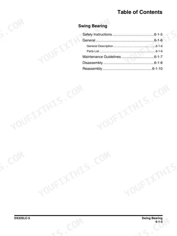
| Lower Structure and Chassis | 779-946 | Swing Bearing, Maintenance Guidelines, Center Joint, Troubleshooting, Testing and Adjustment, Inspection, Testing |
| Front | 947-1006 | Boom and Arm, Arm Removal, Boom Removal, Arm Installation, Boom Installation, Bucket |
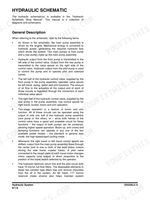
| Hydraulic System | 1007-1088 | Hydraulic Schematic, Hydraulic Component and Oil Flow, Hydraulic Components, Main Oil Circuit, Pilot Oil Circuit, Return Oil Circuit |
| Electrical System | 1089-1258 | Introduction, Electrical Supply System, Engine Starting Circuit, Start Operation, After Start, Engine Preheating System |
| Options | 1259-1350 | One Way, Hydraulic Circuit, Caution for Installation, Installation Procedure, Main Piping - One and Two-Way, Main Piping - One Way |
| Schematic | 1351-1356 | Hydraulic Schematic / Electrical Schematic |
Quick Reference Specifications
| Specification | Value | Page |
|---|---|---|
| DX225LC-5 | ||
| Engine | Doosan DL06 | p. 1355 |
| Fuel tank capacity | 400 L (106 U.S. gal) | p. 92 |
| Swing speed | 16.5 +/-1.7 s per 3 revolutions | p. 99 |
| Low idle | 800 +/-20 rpm | p. 99 |
| standard 600 mm shoes | ||
| Shipping weight | 21.7 tons (47,840 lb) | p. 92 |
| mono / articulated boom | ||
| Bucket digging force | 149 kN, 15,200 kg (33,500 lb) | p. 92 |
| Bucket heaped capacity range | SAE 0.51 - 1.49 m3 (0.67 - 1.95 yd3) | p. 92 |
| standard 600 mm (24") shoe | ||
| Ground pressure | 0.462 bar (6.70 psi) | p. 92 |
| PCSA heaped | ||
| Standard bucket | 0.92 m3 (1.2 yd3) | p. 92 |
| on flat | ||
| Travel speed, 1st gear | 23.0 +/-2.3 s | p. 99 |
Doosan DX225LC-5 Common Problems This Manual Covers
Weak digging or slow cycle times on one or both circuits.
Start with the Hydraulic System section: trace the main oil circuit, pilot oil circuit and return oil circuit against the fold-out schematic, then use the Main Pump section's specifications and theory of operation to test the axial piston pump before condemning it.
Manual Section: Hydraulic System / Upper Structure - Main Pump p. 1007Sticky or erratic control response from the joysticks or travel pedals.
The Swing Device, Joystick and Control Valves section covers the work lever joystick valve, dozer joystick valve, travel control valve with damper, solenoid valve, EPPR valve and accumulator, so you can isolate whether the fault is pilot pressure, a valve spool or an electrical solenoid.
Manual Section: Upper Structure - Swing Device, Joystick and Control Valves p. 651Engine cranks but will not start, or starter stays dead.
The Electrical System section walks the engine starting circuit step by step: electrical supply system, start operation, what happens after start, and the engine preheating system for cold mornings, all cross-referenced to the fold-out electrical schematic EX1404254 with its connector and terminal legend.
Manual Section: Electrical System / Schematic p. 1089Play or noise in the swing bearing, or leaks at the center joint.
The Lower Structure and Chassis section gives swing bearing maintenance guidelines plus center joint troubleshooting, testing and adjustment, inspection and testing procedures, so you can measure actual bearing condition and reseal the center joint instead of guessing at a five figure repair.
Manual Section: Lower Structure and Chassis p. 779Frequently Asked Questions
Does this manual cover main pump rebuild, or just remove and replace?
It goes inside the pump. The Main Pump section covers the axial piston pump with specifications, theory of operation, cautions for operation, required tools and tightening torques, and there is a separate section on the drive coupling with section view, disassembly and reassembly. You can decide from the wear limits whether your pump is worth opening or needs an exchange unit. p. 415
Are the full hydraulic and electrical schematics included?
Yes, and they are the real thing, not simplified diagrams. The book ends with a dedicated Schematic section: the complete DX225LC-5 hydraulic schematic (drawing EX1404250 with a 61-item component legend and an option matrix) and the complete electrical schematic (drawing EX1404254 with connector and terminal legends). Both are large single-sheet fold-outs stamped Serial Number 1001 and Up. p. 1351
My machine has the two piece boom. Does the manual cover it?
Yes. The Specifications section gives overall dimensions and working range for both the one piece and two piece boom, and the Front section walks through arm and boom removal and installation plus the bucket. The counterweight section also carries the warning procedure you need before pulling any front attachment. p. 947
Which engine is in the DX225LC-5, and how deep does the engine coverage go?
The Doosan DL06, named right on the hydraulic schematic. The Engine section covers general information, scheduled maintenance, inspection and repair, engine identification and the data plate, so you can confirm exactly which build you have before ordering parts. It also gives you tune points like the 800 rpm low idle spec. p. 147
Can I check swing and travel performance against factory numbers?
Yes. The book gives measurable pass or fail values: swing speed of 16.5 seconds plus or minus 1.7 per 3 revolutions, first gear travel time of 23.0 seconds plus or minus 2.3. The Lower Structure and Chassis section adds troubleshooting, testing and adjustment procedures, so a stopwatch and this book tell you whether the complaint is real before you start swapping components. p. 99




Reviews
There are no reviews yet.