
Part of the Doosan Repair Manuals.
Every one of the 842 pages in this Doosan DX55 Service Manual PDF (OEM #K1038080E) is aimed at one machine: the DX55 track excavator, from swing bearing to bucket teeth. You get factory hydraulic schematics covering the main pump, control valve, and travel circuits, plus complete wiring diagrams for the starting, preheating, and instrument systems. Inside this shop manual: a full standard torque section for metric and U.S. fasteners, engine work from cylinder head to alternator, and rebuild steps for the swing motor, travel motor, and cylinders. Measure your track links first: 135 mm pitch is standard, 137 mm means replacement time. Then torque the fuel filter to 19.6-23.5 N-m and move on. No more chasing hydraulic problems with borrowed numbers. Bookmarked and keyword-searchable on any device; download it and walk straight to the machine.
What's Inside This Doosan DX55 Manual
| System | Pages | Key Topics |
|---|---|---|
| Track Excavator Safety | 5-48 | Safety Precautions, General Safety Essentials, Location of Safety Labels, Machine Operation, Maintenance, Battery, Towing, Shipping and Transportation |
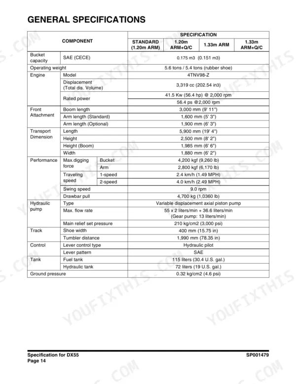
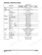
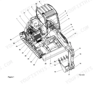
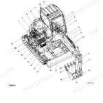
| Specification for DX55 | 49-72 | Component Locations, General Dimensions, Working Range, General Specifications, Engine Performance Curves, Performance Tests, Excavator Performance Standards |
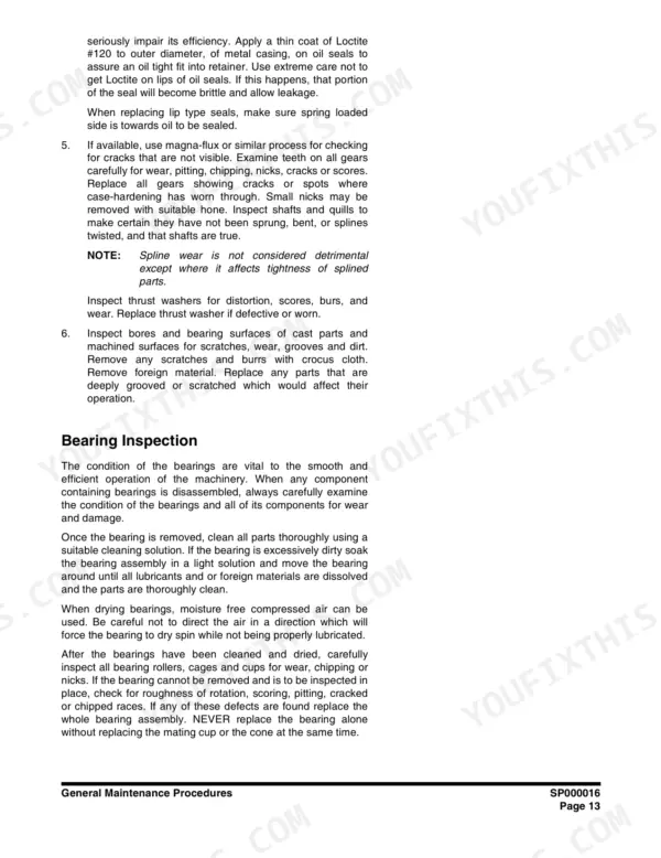
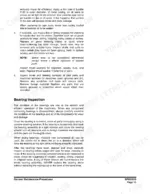
| General Maintenance Procedures | 73-92 | Welding Precautions, Hydraulic System, Maintenance Service and Repair Procedure, Hydraulic System Cleanliness, Oil Leakage Precautions, Cleaning and Inspection, Bearing Inspection |
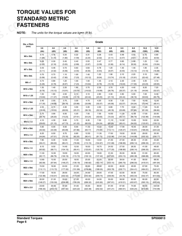
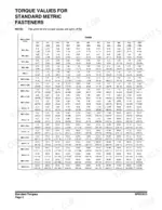
| Standard Torques | 93-108 | Metric Fasteners, U.S. Fasteners, Type 8 Phosphate Coated Hardware, Hose Clamps, Split Flanges, Torque Wrench Extension Tools |
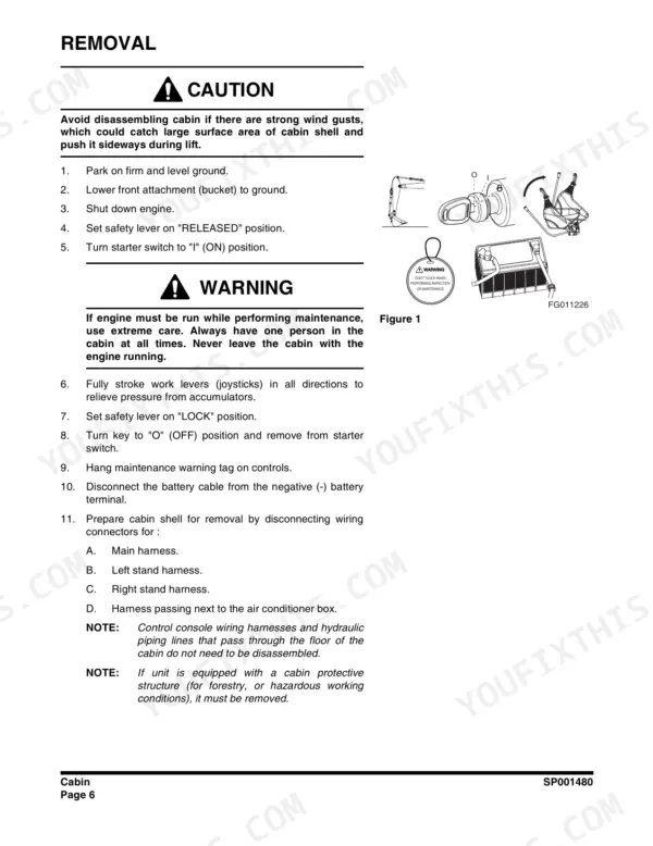
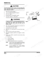
| Cabin | 109-118 | Cabin Shell Removal and Installation, Main and Stand Wiring Harness Disconnection, Air Conditioner Box Harness, Control Console Harnesses and Hydraulic Lines, Cabin Weight 290 Kg (639 Lb) Lifting Precaution |
| Swing Bearing | 119-126 | Operating Recommendation, Axial Play, Lateral Play, Basic Operation, Rebuilding |
| Track Assembly | 127-160 | Track Tension, Cleaning and Inspection, Idler, Lower Roller, Upper Roller, Sprocket, Track Removal and Installation |
| Engine | 161-422 | General Service Information, Periodic Maintenance, Cylinder Head, Fuel System, Cooling System, Lubrication System, Starter Motor, Alternator |
| Drive Coupling (Main Pump) | 423-430 | Safety Precautions, Installation Procedure, Precaution |
| Accumulator | 431-438 | Safety Precautions, General Description, Specifications |
| Center Joint (Swivel) | 439-448 | Safety Precautions, General Description, Troubleshooting, Testing, Adjustment, Disassembly, Assembly |
| Cylinders | 449-476 | Safety Precautions, Theory of Operation, Special Tools, Materials, Disassembly, Assembly |
| Swing Motor | 477-526 | Safety Precautions, Description of Functions, Operation, Precautions for Handling, Periodic Inspection, Troubleshooting, Service Manual |
| Travel Motor | 527-598 | Safety Precautions, General, Operating Principle, Special Tools, Materials, Troubleshooting, Disassembly |
| Main Control Valve | 599-650 | Safety Precautions, Composition, Function, Operation, Disassembly, Cleaning, Inspection, Assembly |
| Main Pump | 651-704 | Safety Precautions, General Description, Operation Principle, Function of Components, Adjustment, Installation, Driving, Hydraulic Oil |
| Remote Control Valve (Work Lever / Joystick) | 705-720 | Structure Diagram, Performance Specification, Hydraulic Pressure Circuit Diagram, Disassembly Method, Assembly Method |
| Dozer Valve | 721-734 | Structure Diagram, Performance Specification, Hydraulic Pressure Circuit Diagram, Disassembly, Assembly Method |
| Pedal Valve | 735-754 | Maintenance, Maintenance Standard, Disassembly, Assembly, Troubleshooting |
| Hydraulic Schematic (DX55) | 755-760 | Safety Precautions, Applicable Models, DX55 Hydraulic Circuit Diagram (Publication SP001492) |
| Electrical System | 761-814 | Electrical Supply System, Engine Starting, Engine Preheating System, Instrument System, Engine Control Dial, Refrigerant Circulation |
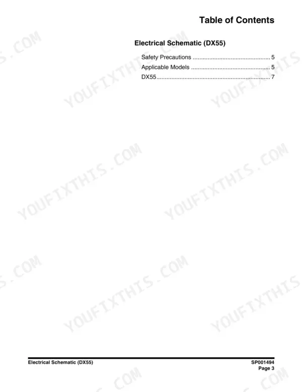
| Electrical Schematic (DX55) | 815-820 | Safety Precautions, Applicable Models, DX55 Electrical Circuit Diagram (Publication SP001494) |
| Boom and Arm | 821-832 | Front Attachment Pin Specifications, Front Attachment Removal and Installation, Arm Removal Procedure, Boom Removal Procedure, Arm Installation Procedure |
| Bucket | 833-842 | Bucket Tooth Inspection and Replacement, Bucket O-Ring Replacement, Bucket Attachment Removal and Reversal |
Quick Reference Specifications
| Specification | Value | Page |
|---|---|---|
| Link Pitch Standard | 135 mm (5.32 in) | p. 138 |
| Link Pitch Limit | 137 mm (5.4 in) | p. 138 |
| Fuel filter tightening torque | 14 - 17 ft•lb (19.6 - 23.5 N•m) | p. 232 |
| Fuel filter / water separator retaining ring torque | 11 - 15 ft•lb (15 - 20 N•m) | p. 246 |
| Engine oil drain plug torque | 14 - 17 ft•lb (19.6 - 23.5 N•m) | p. 228 |
| V-belt deflection force | 22 ft•lb (98 N•m) | p. 231 |
| Used V-belt deflection (Position A) | 3/8 - 1/2 in. (10 - 14 mm) | p. 231 |
| Air cleaner element cleaning air pressure | 42 - 71 psi (0.29 - 0.49 MPa) | p. 237 |
| Hydraulic filter replacement interval | 500 hours | p. 668 |
| Engine Coolant Temperature Sensor (50°C) | Over 188.2Ω | p. 779 |
| Engine Coolant Temperature Sensor (67°C) | 102Ω | p. 779 |
| Engine Rated Power | 41.5 Kw (56.4 hp) @ 2,000 rpm | p. 62 |
Doosan DX55 Common Problems This Manual Covers
Doosan DX55 engine cranks slow or won't start, battery goes dead overnight between shifts
Load test the battery and clean both cable ends before condemning the starter. Check charging output at the alternator; it is rated at 40 amps, spec on page 394. Trace the start circuit against the wiring diagram on page 816, then hunt parasitic draw with a meter in series and everything switched off.
Manual Section: Electrical System p. 761Water in fuel, hard starting and rough idle after refueling from a farm tank
Drain the water separator daily and replace the element if the fuel looks cloudy. Reinstall the separator cup and tighten the retaining ring to 11-15 ft-lb (15-20 N-m), spec on page 246. Replace the fuel filter, torque it to 14-17 ft-lb per page 232, then bleed the system and check the suction side for air leaks.
Manual Section: Engine p. 246Track runs loose and machine pulls to one side, chain jumps the sprocket on slopes
Adjust track tension through the grease fitting and torque the grease valve to 59-88 Nm when finished, spec on page 135. Measure link pitch across four links: standard is 135 mm (5.32 in), replace the chain at 137 mm, wear limits on page 138. Compare wear side to side before blaming the travel motor.
Manual Section: Track Assembly p. 135Hydraulics weak and slow after warm-up, boom struggles under load and cycle times drag
Check hydraulic oil level with the machine cold and replace the return filter; it is due every 500 hours, interval on page 668. Test main relief pressure at the pump: spec is 210 kg/cm2 (3,000 psi) per page 62. If pressure and flow both fall off when the oil is hot, pull the main pump for inspection, procedures start on page 651.
Manual Section: Main Pump p. 668Engine runs hot in summer, coolant temperature gauge climbs during heavy trenching work
Clean the radiator and cooler fins with compressed air from the fan side out, keeping nozzle pressure between 42 and 71 psi (0.29-0.49 MPa), spec on page 237. Verify coolant level; the system holds 4.2 liters. Test the coolant temperature sensor before trusting the gauge: it should read over 188.2 ohms at 50°C, values on page 779.
Manual Section: Engine p. 779Frequently Asked Questions
What are the replacement specifications for the fuel filter?
The fuel filter should be replaced every 500 hours of operation. When installing a new filter, turn it to the right until it contacts the mounting surface, then tighten an additional 3/4 of a turn using a filter wrench. p. 232
What is the tightening torque for the fuel injection pump drive gear nut?
The tightening torque for the fuel injection pump drive gear nut is 83 - 90 ft-lb (113 - 123 N-m; 11.5 - 12.5 kgf-m). p. 261
What is the standard valve clearance for the engine?
The standard intake and exhaust valve clearance for all models (except where specified) is 0.006 - 0.010 in. (0.15 - 0.25 mm). p. 207
What is the tightening torque for the cylinder head bolts?
The cylinder head bolts must be tightened to 76 - 83 ft-lb (103.1 - 112.9 N-m; 8.7 - 9.3 kgf-m). p. 261
How often should the engine oil and oil filter be changed?
The engine oil and oil filter should be changed after the first 50 hours of operation and then every 250 hours thereafter. p. 201
What format is this Doosan DX55 manual in?
This is a 842-page searchable PDF ready for immediate download. Works on any device, so pull it up on your phone while you're under the hood. No shipping, no waiting.
Is printing allowed for this Doosan DX55 Service Manual?
Yes. Printing works from any reader and any printer, for your own shop use.







Reviews
There are no reviews yet.